AIR COMPRESSOR REMOVAL

CAUTION / NOTICE / HINT
The necessary procedures (adjustment, calibration, initialization, or registration) that must be performed after parts are removed, installed, or replaced during the FC air compressor with motor assembly removal/installation are shown below.
| Replacement Part or Procedure | Necessary Procedure | Effects/Inoperative when not Performed | Link |
|---|---|---|---|
| Front wheel alignment adjustment |
|
VSC malfunctioning | |
| Adjust lane departure warning camera | Lane departure alert system does not operate correctly |
CAUTION:
-
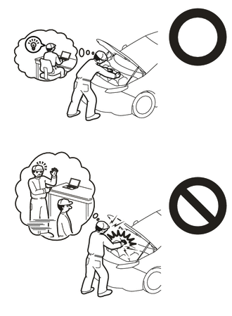
This vehicle has contains high voltage circuits standardized with orange colored wiring and connectors, so follow the instructions in this manual to perform the procedures correctly.
-
If the correct procedures are not followed according to the instructions in this manual, there is a danger of electric shock from the high voltage circuits.
-
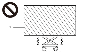
*a Heavy object exceeding the capacity of the engine lifter Because the weight of the FCV transaxle with FC air compressor assembly is extremely heavy, make sure to follow the work procedures described in the repair manual.
-
If work is not performed according to the procedures described in the repair manual, there is a danger that the engine lifter could drop and components could fall down.
-

Be sure to wear insulating gloves when working on high voltage wiring or components.
-
If work is performed without wearing insulating gloves, there is a danger of electric shock.
Note
When the vehicle is parked with the power switch off, if the FC control ECU judges that the FC stack temperature will go below 0°C (32°F), it activates the FC air compressor, hydrogen pump and FC cooling water pump for a maximum of 180 seconds and drains water from the FC stack assembly. When performing inspection or repairs with the power switch off (not on (IG) or on (READY)), disconnect the cable from the negative (-) auxiliary battery terminal before performing work.
PROCEDURE
-
CAUTIONS FOR HIGH VOLTAGE SYSTEM COMPONENTS
-
CAUTIONS FOR COOLANT (FC STACK COOLANT)
-
CAUTIONS FOR INTAKE SYSTEM COMPONENTS
Note
-
If the intake passages are contaminated with foreign matter such as metal fragments or resin fragments, the FC air compressor and FC stack could be damaged as a result.
-
When intake system components have been removed, protect the openings of the removed intake system components, and the components they were connected to, from foreign matter contamination by covering them with plastic bags.
-
Before installing intake system components, check that no foreign matter has entered through the openings.
-
When intake system components have been removed, if the rubber parts of connecting portions are stuck, or the wiring is damaged, etc., replace the affected components with new ones.
-
When connecting the hose of the intake system, do not use any lubricants such as grease or oil.
-
-
REMOVE SERVICE PLUG GRIP (for EV)
-
REMOVE FC STACK SERVICE PLUG GRIP
-
REMOVE FRONT BUMPER LOWER ABSORBER
-
REMOVE NO. 3 RADIATOR AIR GUIDE
-
REMOVE NO. 1 MOTOR UNDER COVER
-
REMOVE NO. 2 MOTOR UNDER COVER
-
REMOVE REAR MOTOR UNDER COVER LH
-
REMOVE REAR MOTOR UNDER COVER RH
-
REMOVE FRONT FLOOR COVER LH
-
REMOVE FRONT FLOOR COVER RH
-
REMOVE SUSPENSION MEMBER TO FRONT CROSSMEMBER BRACE SUB-ASSEMBLY
-
DRAIN HYBRID TRANSAXLE FLUID
-
DRAIN COOLANT (for Inverter)
-
DRAIN COOLANT (FC STACK COOLANT)
-
REMOVE WINDSHIELD WIPER MOTOR AND LINK
-
REMOVE NO. 2 HEATER AIR DUCT SPLASH SHIELD SEAL (for LHD)
-
REMOVE NO. 1 HEATER AIR DUCT SPLASH SHIELD SEAL (for RHD)
-
REMOVE WATER GUARD PLATE LH (for LHD)
-
REMOVE WATER GUARD PLATE RH (for RHD)
-
REMOVE COWL BODY MOUNTING REINFORCEMENT RH (for LHD)
-
REMOVE COWL BODY MOUNTING REINFORCEMENT RH (for RHD)
-
REMOVE OUTER COWL TOP PANEL SUB-ASSEMBLY (for LHD)
-
REMOVE OUTER COWL TOP PANEL SUB-ASSEMBLY (for RHD)
-
REMOVE COOL AIR INTAKE DUCT SEAL
-
REMOVE AIR CLEANER INLET
-
Remove the bolt and clip to separate the air cleaner inlet from the hood lock support sub-assembly.
-
Remove the air cleaner inlet from the air cleaner with element assembly.
Note
During removal, make sure not to damage the sponges at the inlet side and outlet side of the air cleaner inlet.
-
-
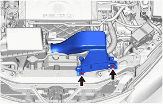
REMOVE AIR CLEANER WITH ELEMENT ASSEMBLY
-
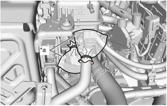
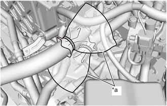
Loosen the hose clamp and disconnect the air cleaner hose assembly from the air cleaner with element assembly.
Note
Do not damage the port or hose inner surface during disconnection.
-
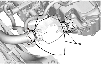
*a Plastic Bag To prevent contamination by foreign matter or water droplets, cover the connecting portions of the air cleaner hose assembly and air cleaner with element assembly with plastic bags.
-
Disconnect the connector of the intake mass air flow meter sub-assembly.
-
Disengage the clamp to separate the wire harness from the air cleaner with element assembly.
-
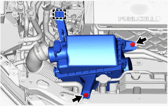
Remove the 2 bolts to separate the air cleaner with element assembly from the hood lock support sub-assembly and inverter protector.
-
Disengage the pin to remove the air cleaner with element assembly from the FC inverter input junction assembly.
-
-
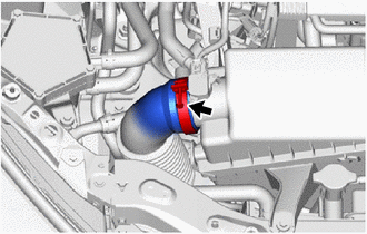
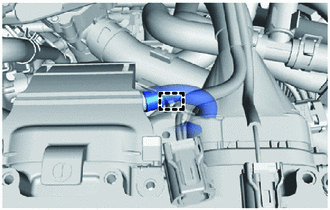
REMOVE AIR CLEANER HOSE ASSEMBLY
-
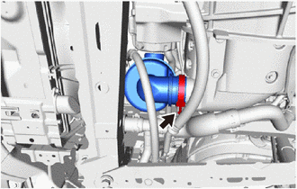
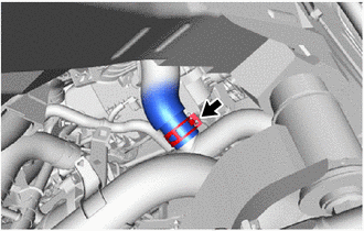
Loosen the hose clamp and remove the air cleaner hose assembly from the FC air compressor with motor assembly.
Note
Do not damage the port or hose inner surface during disconnection.
-
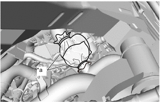
*a Plastic Bag To prevent contamination by foreign matter or water droplets, cover the connecting portions of the air cleaner hose assembly and FC air compressor with motor assembly with plastic bags.
-
-
REMOVE INVERTER COVER
-
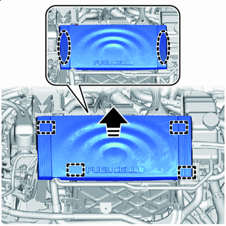

Place Hands Here 
Remove in this Direction Disengage the 4 grommets to remove the inverter cover from the inverter with converter assembly and inverter protector.
Note
To prevent damage to the inverter cover, lift it upward and disengage the grommets.
-
-
REMOVE INVERTER TERMINAL COVER
-
CHECK TERMINAL VOLTAGE
-
TEMPORARILY TIGHTEN INVERTER TERMINAL COVER
-
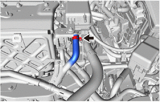
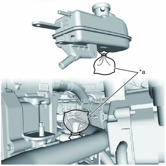
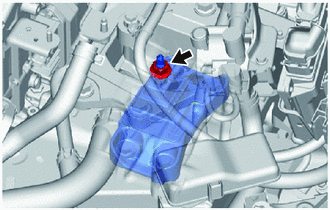
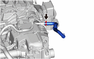
DISCONNECT NO. 2 INVERTER DRAIN HOSE
-
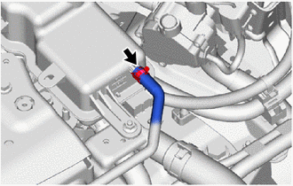
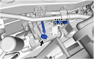
Slide the hose clip and disconnect the No. 2 inverter drain hose from the inverter reserve tank assembly.
Note
-
Do not damage the port or hose inner surface during disconnection.
-
Perform the procedures by hand. Do not use any tools.
-
-
*a Plastic Bag To prevent contamination by foreign matter or water droplets, cover the connecting portions of the No. 2 inverter drain hose and inverter reserve tank assembly with plastic bags.
-
-
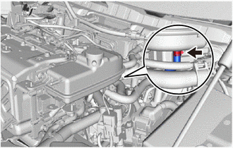
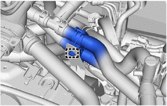
DISCONNECT NO. 2 INVERTER COOLING HOSE
-
Slide the hose clip and disconnect the No. 2 inverter cooling hose from the inverter reserve tank assembly.
Note
-
Do not damage the port or hose inner surface during disconnection.
-
Perform the procedures by hand. Do not use any tools.
-
-
*a Plastic Bag To prevent contamination by foreign matter or water droplets, cover the connecting portions of the No. 2 inverter cooling hose and inverter reserve tank assembly with plastic bags.
-
-
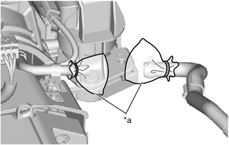
REMOVE INVERTER RESERVE TANK ASSEMBLY
-
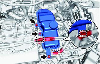
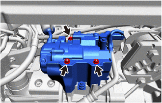
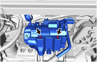
Disengage the 3 clamps to separate the wire harness from the inverter reserve tank assembly.
-
Remove the 2 bolts and nut to separate the inverter reserve tank assembly from the inverter with converter assembly and inverter protector.
-
Slide the hose clip and disconnect the No. 1 inverter drain hose from the inverter reserve tank assembly.
Note
-
Do not damage the port or hose inner surface during disconnection.
-
Perform the procedures by hand. Do not use any tools.
-
-
*a Plastic Bag To prevent contamination by foreign matter or water droplets, cover the connecting portions of the No. 1 inverter drain hose and inverter reserve tank assembly with plastic bags.
-
-
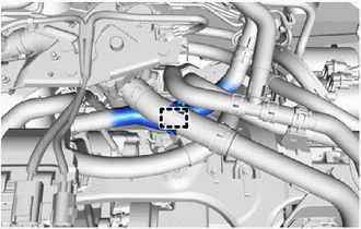
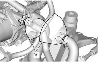
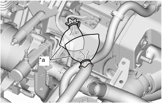
SEPARATE HEATER WATER INLET B HOSE
-
Disengage the clamp to separate the heater water inlet B hose from the FC radiator inlet pipe.
-
-
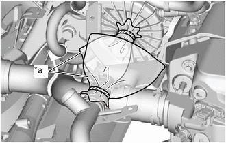
SEPARATE NO. 2 WATER HOSE SUB-ASSEMBLY
-
Disengage the clamp to separate the No. 2 water hose sub-assembly from the No. 1 FC cooling water valve outlet hose.
-
-
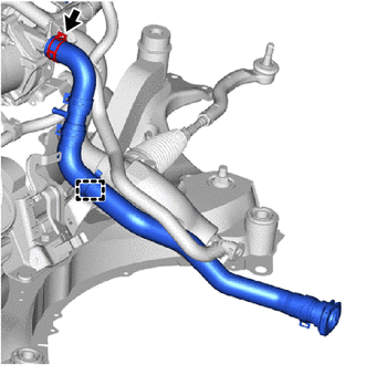
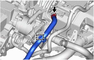
DISCONNECT FC RADIATOR INLET HOSE
-
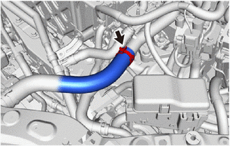
Slide the hose clip and disconnect the FC radiator inlet hose from the FC radiator inlet pipe.
Note
-
Do not damage the port or hose inner surface during disconnection.
-
Perform the procedures by hand. Do not use any tools.
-
-
*a Plastic Bag To prevent contamination by foreign matter or water droplets, cover the connecting portions of the FC radiator inlet hose and FC radiator inlet pipe with plastic bags.
-
-
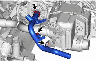
REMOVE FC RADIATOR INLET PIPE
-
Remove the 2 bolts to separate the FC radiator inlet pipe from the center frame crossmember sub-assembly.
-
Slide the hose clip and remove the No. 1 FC cooling water valve outlet hose from the FC cooling water temperature control valve.
Note
-
Do not damage the port or hose inner surface during disconnection.
-
Perform the procedures by hand. Do not use any tools.
-
-
*a Plastic Bag To prevent contamination by foreign matter or water droplets, cover the connecting portions of the No. 1 FC cooling water valve outlet hose and FC cooling water temperature control valve with plastic bags.
-
-
REMOVE FC COOLING WATER TEMPERATURE CONTROL VALVE
-
DISCONNECT INTERCOOLER COOLING WATER OUTLET HOSE
-
Slide the hose clip and disconnect the intercooler cooling water outlet hose from the FC cooling water valve inlet pipe.
Note
-
Do not damage the port or hose inner surface during disconnection.
-
Perform the procedures by hand. Do not use any tools.
-
-
*a Plastic Bag To prevent contamination by foreign matter or water droplets, cover the connecting portions of the intercooler cooling water outlet hose and FC cooling water valve inlet pipe with plastic bags.
-
-
DISCONNECT NO. 2 EV RADIATOR INLET HOSE
-
Disengage the clamp to separate the No. 2 EV radiator inlet hose from the EV water pump outlet pipe.
-
Slide the hose clip and disconnect the No. 2 EV radiator inlet hose from the EV radiator inlet pipe.
Note
-
Do not damage the port or hose inner surface during disconnection.
-
Perform the procedures by hand. Do not use any tools.
-
-
*a Plastic Bag To prevent contamination by foreign matter or water droplets, cover the connecting portions of the No. 2 EV radiator inlet hose and EV radiator inlet pipe with plastic bags.
-
-
DISCONNECT FC WATER PUMP DRAIN HOSE ASSEMBLY
-
Remove the bolt to separate the FC water pump drain hose assembly from the FC inverter input junction assembly.
-
Disengage the 3 clamps to separate the FC water pump drain hose assembly from the No. 2 FC cooling water pump cable bracket.
-
-
REMOVE FC INVERTER INPUT JUNCTION COVER
-
DISCONNECT FRAME WIRE
-
REMOVE INVERTER TERMINAL COVER
-
REMOVE FC INVERTER INPUT JUNCTION ASSEMBLY
-
DISCONNECT MOTOR CABLE
CAUTION:
Wear insulated gloves.
Note
Do not allow foreign matter or water droplets to enter the inverter with converter assembly.
-
Using an insulated tool, remove the 5 bolts and disconnect the motor cable from the inverter with converter assembly.
Note
-
Do not damage the terminals, connector housings or inverter with converter assembly during disconnection.
-
Do not touch the connector rubber seal or terminals.
-
Insulate the disconnected terminals with insulating tape.
-
-
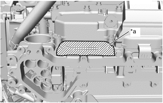
*a Protective Tape To prevent contamination by foreign matter or water droplets, cover the opening of the inverter with converter assembly with protective tape.
-
Disengage the clamp to separate the motor cable from the motor cable bracket.
-
-
DISCONNECT FC AIR COMPRESSOR CABLE
CAUTION:
Wear insulated gloves.
Note
Do not allow foreign matter or water droplets to enter the inverter with converter assembly.
-
Using an insulated tool, remove the 5 bolts and disconnect the FC air compressor cable from the inverter with converter assembly.
Note
-
Do not damage the terminals, connector housings or inverter with converter assembly during disconnection.
-
Do not touch the connector rubber seal or terminals.
-
Insulate the disconnected terminals with insulating tape.
-
-
*a Protective Tape To prevent contamination by foreign matter or water droplets, cover the opening of the inverter with converter assembly with protective tape.
-
Disengage the clamp to separate the FC air compressor cable from the motor cable bracket.
-
-
TEMPORARILY TIGHTEN INVERTER TERMINAL COVER
-
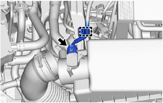
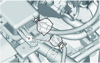
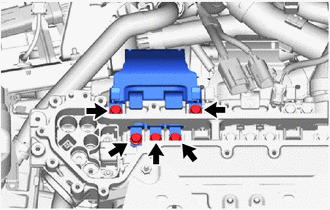
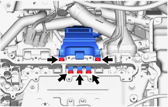
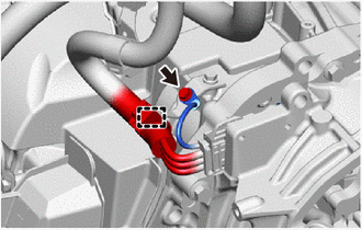
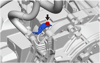
DISCONNECT FC COOLING WATER PUMP CABLE
CAUTION:
Wear insulated gloves.
-
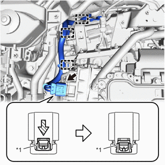
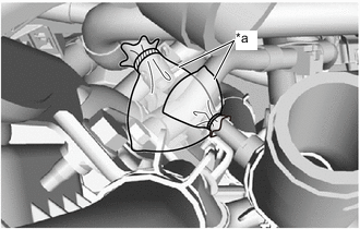
*1 Green-colored Lock As shown in the illustration, pull out the green-colored lock of the connector and disconnect the FC cooling water pump cable connector.
Note
-
Do not touch the connector terminals.
-
Insulate the disconnected terminals with insulating tape.
-
-
Disengage the 3 clamps to separate the FC cooling water pump cable.
-
-
REMOVE UPPER NO. 1 RELAY BLOCK COVER
-
REMOVE NO. 1 RELAY BLOCK COVER
-
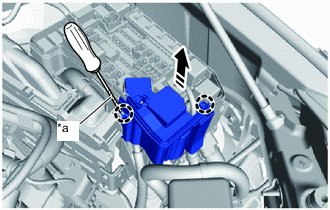
*a Protective Tape Remove in this Direction Using a thin-bladed screwdriver with its tip wrapped in protective tape, disengage the 2 claws and remove the No. 1 relay block cover from the motor compartment relay block.
-
-
DISCONNECT MOTOR WIRE
-
Disconnect the 4 connectors.
-
Remove the 3 bolts to disconnect the motor wire.
-
Disengage the 4 clamps to separate the motor wire.
-
-
DISCONNECT FCV TRACTION MOTOR BOND CABLE ASSEMBLY
-

Remove the bolt to disconnect the FCV traction motor bond cable assembly from the center frame crossmember sub-assembly.
-
-
PLACE FRONT WHEELS FACING STRAIGHT AHEAD
-
SECURE STEERING WHEEL
-
REMOVE COLUMN HOLE COVER SILENCER SHEET
-
DISCONNECT NO. 2 STEERING INTERMEDIATE SHAFT ASSEMBLY
-
SEPARATE NO. 1 STEERING COLUMN HOLE COVER SUB-ASSEMBLY
-
REMOVE FRONT DRIVE SHAFT ASSEMBLY
-
REMOVE REAR SIDE RAIL REINFORCEMENT SUB-ASSEMBLY LH
-
REMOVE REAR SIDE RAIL REINFORCEMENT SUB-ASSEMBLY RH
-
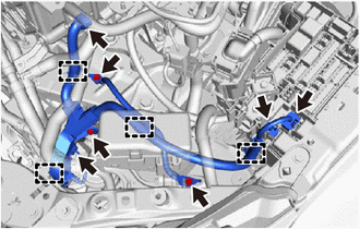
SEPARATE FC CONVERTER POWER OUTLET CABLE
CAUTION:
Wear insulated gloves.
-
Disengage the clamp to separate the FC converter power outlet cable from the rear motor mounting insulator.
-
-
SEPARATE HYDROGEN PUMP INVERTER CABLE
CAUTION:
Wear insulated gloves.
-
Disengage the 2 clamps to separate the hydrogen pump inverter cable from the rear motor mounting insulator.
-
-
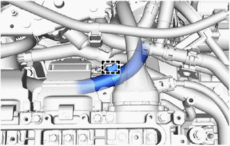
SEPARATE NO. 2 INVERTER COOLING OUTLET HOSE
-
Disengage the clamp to separate the No. 2 inverter cooling outlet hose from the rear motor mounting insulator.
-
-
SEPARATE NO. 2 FC COOLING WATER VALVE INLET HOSE
-
Disengage the clamp to separate the No. 2 FC cooling water valve inlet hose from the rear motor mounting insulator.
-
-
DISCONNECT NO. 2 EV WATER HOSE CONNECTOR
-
SEPARATE FC CONVERTER COOLING WATER OUTLET HOSE
-
Disengage the clamp to separate the FC converter cooling water outlet hose from the vehicle body.
-
-
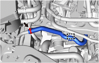
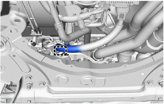
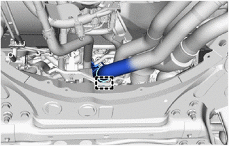
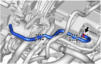
DISCONNECT NO. 2 FC AIR COMPRESSOR OUTLET HOSE
-
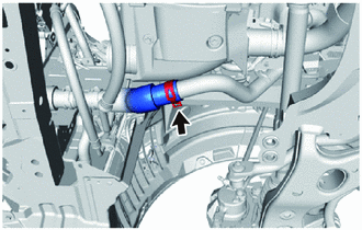
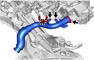
Loosen the hose clamp and disconnect the No. 2 FC air compressor outlet hose from the No. 2 FC air compressor outlet pipe.
Note
Do not damage the port or hose inner surface during disconnection.
-
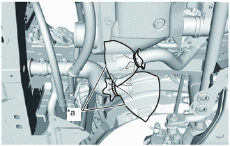
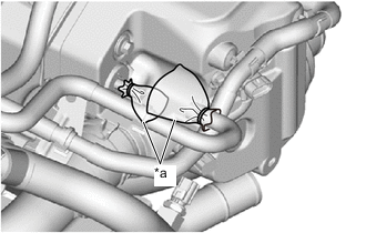
*a Plastic Bag To prevent contamination by foreign matter or water droplets, cover the connecting portions of the No. 2 FC air compressor outlet hose and No. 2 FC air compressor outlet pipe with plastic bags.
-
-
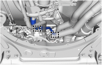
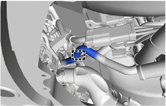
DISCONNECT NO. 2 FC COOLING BY-PASS HOSE
-
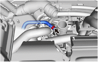
Slide the hose clip and disconnect the No. 2 FC cooling by-pass hose from the FC cooling water pump inlet pipe.
Note
-
Do not damage the port or hose inner surface during disconnection.
-
Perform the procedures by hand. Do not use any tools.
-
-
*a Plastic Bag To prevent contamination by foreign matter or water droplets, cover the connecting portions of the No. 2 FC cooling by-pass hose and FC cooling water pump inlet pipe with plastic bags.
-
-
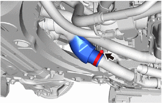
DISCONNECT NO. 2 FC RADIATOR OUTLET HOSE
-
Slide the hose clip and disconnect the No. 2 FC radiator outlet hose from the FC cooling water pump inlet pipe.
Note
-
Do not damage the port or hose inner surface during disconnection.
-
Perform the procedures by hand. Do not use any tools.
-
-
*a Plastic Bag To prevent contamination by foreign matter or water droplets, cover the connecting portions of the No. 2 FC radiator outlet hose and FC cooling water pump inlet pipe with plastic bags.
-
-
DISCONNECT NO. 3 MOTOR COOLING HOSE
-
DISCONNECT NO. 1 MOTOR COOLING HOSE
-
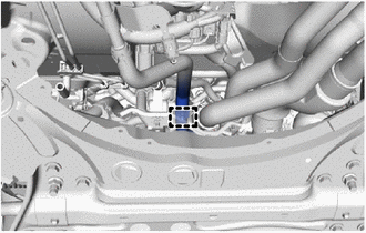
SEPARATE COMPRESSOR WITH MOTOR ASSEMBLY
CAUTION:
Wear insulated gloves.
-
Disconnect the connector.
-
Disengage the clamp to separate the compressor cable from the wire harness clamp bracket.
-
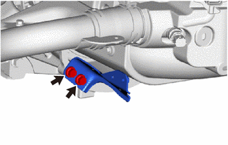
Remove the bolt and 2 nuts from the compressor with motor assembly.
-
Using an E8 "TORX" socket wrench, remove the 2 stud bolts to separate the compressor with motor assembly from the FC air compressor with motor assembly.
-
-
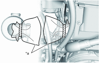
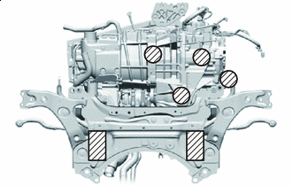
REMOVE FCV TRANSAXLE WITH MOTOR ASSEMBLY
-
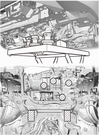

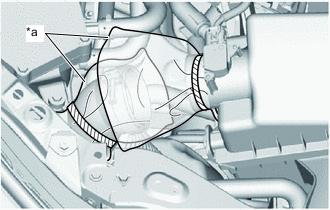
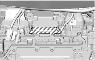
Attachment Placement Positions Using a height adjustment attachment and a plate lift attachment, support the FC air compressor with motor assembly, FCV transaxle with motor assembly and front suspension crossmember sub-assembly with a engine lifter.
Note
-
Using a height adjustment attachment, set the FC air compressor with motor assembly and the FCV transaxle with motor assembly so that they are horizontal and level.
-
For the front suspension crossmember sub-assembly, set the height adjustment attachment and plate lift attachment so that they are lightly contacting.
-
-
Remove the nut to separate the motor mounting bracket LH from the motor mounting insulator LH.
-
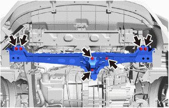
Remove the 7 bolts and the front crossmember sub-assembly from the front motor mounting insulator and vehicle body.
-
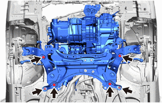
Remove the 6 bolts to separate the front suspension member rear brace LH, front suspension member rear brace RH and front suspension crossmember sub-assembly from the vehicle body.
-
Operate the engine lifter to slowly remove the FC air compressor with motor assembly, FCV transaxle with motor assembly and front suspension crossmember sub-assembly from the vehicle body.
Note
Make sure that the FC air compressor with motor assembly, FCV transaxle with motor assembly and front suspension crossmember sub-assembly are clear of all wire harnesses and hoses.
-
-
DISCONNECT MOTOR WIRE
-
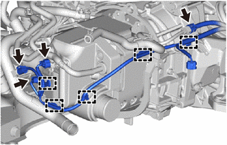
Disconnect the 4 connectors.
-
Disengage the 5 clamps to separate the motor wire from the FC air compressor with motor assembly.
-
-
REMOVE WIRE HARNESS CLAMP BRACKET
-
Disengage the clamp to separate the FC air compressor revolution sensor wire from the wire harness clamp bracket.
-
Remove the bolt and wire harness clamp bracket from the FC air compressor bracket.
-
-
REMOVE FCV TRACTION MOTOR BOND CABLE ASSEMBLY
-
Remove the 2 bolts and FCV traction motor bond cable assembly from the FC air compressor bracket and FCV transaxle with motor assembly.
-
-
REMOVE FC WATER PUMP DRAIN HOSE ASSEMBLY
-
Slide the hose clip and remove the FC water pump drain hose assembly from the FC cooling water pump assembly.
Note
-
Do not damage the port or hose inner surface during disconnection.
-
Perform the procedures by hand. Do not use any tools.
-
-
*a Plastic Bag To prevent contamination by foreign matter or water droplets, cover the connecting portions of the FC water pump drain hose assembly and FC cooling water pump assembly with plastic bags.
-
-
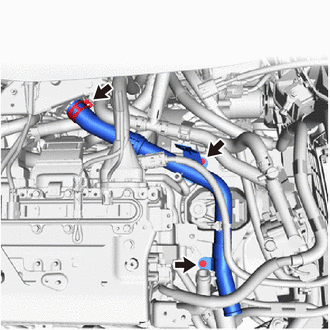
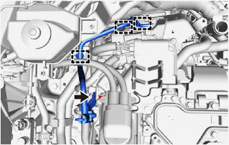
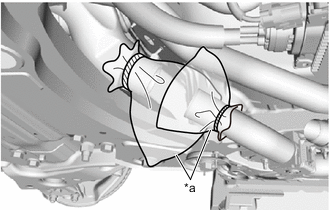
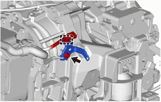
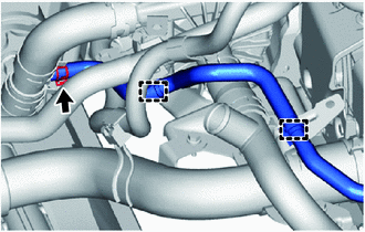
REMOVE INTERCOOLER COOLING WATER OUTLET HOSE
-
Disengage the 2 clamps to separate the intercooler cooling water outlet hose from the No. 3 FC air compressor outlet pipe bracket and FC cooling water pump inlet pipe.
-
Slide the hose clip and remove the intercooler cooling water outlet hose from the FC air compressor with motor assembly.
Note
-
Do not damage the port or hose inner surface during disconnection.
-
Perform the procedures by hand. Do not use any tools.
-
-
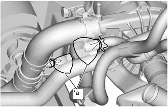
*a Plastic Bag To prevent contamination by foreign matter or water droplets, cover the connecting portions of the intercooler cooling water outlet hose and air FC air compressor with motor assembly with plastic bags.
-
-
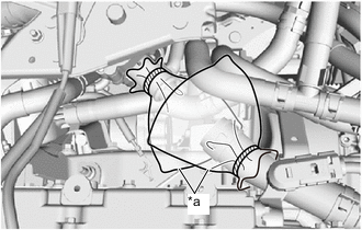
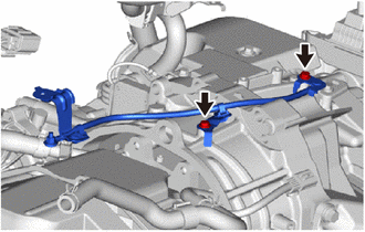
DISCONNECT INTERCOOLER COOLING WATER INLET HOSE
-
Disengage the 2 clamps to separate the intercooler cooling water inlet hose from the No. 3 FC air compressor outlet pipe bracket and FC cooling water pump inlet pipe.
-
Slide the hose clip and disconnect the intercooler cooling water inlet hose from the No. 1 FC cooling water pump outlet hose.
Note
-
Do not damage the port or hose inner surface during disconnection.
-
Perform the procedures by hand. Do not use any tools.
Tech Tips
When removing the intercooler cooling water inlet hose, first remove the FC air compressor lower cover, and then remove the intercooler cooling water inlet hose.
-
-
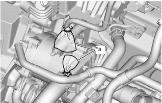
*a Plastic Bag To prevent contamination by foreign matter or water droplets, cover the connecting portions of the intercooler cooling water inlet hose and No. 1 FC cooling water pump outlet hose with plastic bags.
-
-
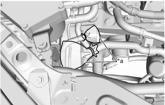
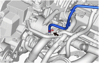
REMOVE NO. 1 FC COOLING WATER PUMP OUTLET HOSE
-
Disengage the clamp to separate the No. 1 FC cooling water pump outlet hose from the FC stack cooling water outlet bracket.
-
Slide the hose clip and remove the No. 1 FC cooling water pump outlet hose from the FC cooling water pump assembly.
Note
-
Do not damage the port or hose inner surface during disconnection.
-
Perform the procedures by hand. Do not use any tools.
-
-
*a Plastic Bag To prevent contamination by foreign matter or water droplets, cover the connecting portions of the No. 1 FC cooling water pump outlet hose and FC cooling water pump assembly with plastic bags.
-
-
REMOVE NO. 2 EV RADIATOR INLET HOSE
-
Slide the hose clip and remove the No. 2 EV radiator inlet hose from the FC air compressor with motor assembly.
Note
-
Do not damage the port or hose inner surface during disconnection.
-
Perform the procedures by hand. Do not use any tools.
-
-
*a Plastic Bag To prevent contamination by foreign matter or water droplets, cover the connecting portions of the No. 2 EV radiator inlet hose and FC air compressor with motor assembly with plastic bags.
-
-
REMOVE FC CONVERTER COOLING WATER OUTLET HOSE
-
Disengage the clamp to separate the FC converter cooling water outlet hose from the No. 3 FC air compressor outlet pipe bracket.
-
Slide the hose clip and remove the FC converter cooling water outlet hose from the FC air compressor with motor assembly.
Note
-
Do not damage the port or hose inner surface during disconnection.
-
Perform the procedures by hand. Do not use any tools.
-
-
*a Plastic Bag To prevent contamination by foreign matter or water droplets, cover the connecting portions of the FC converter cooling water outlet hose and FC air compressor with motor assembly with plastic bags.
-
-
REMOVE FC COOLING WATER PUMP INLET PIPE
-
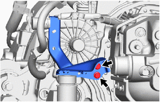
Remove the 2 bolts to separate the FC cooling water pump inlet pipe from the FC cooling water pump inlet bracket and No. 1 FC air compressor outlet pipe.
-
Slide the hose clip and remove the FC cooling water pump inlet pipe from the FC cooling water pump assembly.
Note
-
Do not damage the port or hose inner surface during disconnection.
-
Perform the procedures by hand. Do not use any tools.
-
-
*a Plastic Bag To prevent contamination by foreign matter or water droplets, cover the connecting portions of the FC cooling water pump inlet hose and FC cooling water pump assembly with plastic bags.
-
-
REMOVE FC COOLING WATER PUMP INLET BRACKET
-
Remove the 2 bolts and FC cooling water pump inlet bracket from the FC air compressor bracket.
-
-
REMOVE NO. 1 FC AIR COMPRESSOR OUTLET PIPE
-
Disengage the clamp to separate the FC cooling water pump cable from the No. 1 FC air compressor outlet pipe.
-
Remove the 2 bolts to separate the No. 1 FC air compressor outlet pipe from the No. 3 FC air compressor outlet pipe bracket.
-
Loosen the hose clamp and remove the No. 1 FC air compressor outlet hose from the FC air compressor with motor assembly.
Note
Do not damage the port or hose inner surface during disconnection.
-
*a Plastic Bag To prevent contamination by foreign matter or water droplets, cover the connecting portions of the No. 1 FC air compressor outlet hose and FC air compressor with motor assembly with plastic bags.
-
-
REMOVE NO. 3 FC AIR COMPRESSOR OUTLET PIPE BRACKET
-
Remove the 2 bolts and No. 3 FC air compressor outlet pipe bracket from the FC air compressor bracket.
-
-
REMOVE FC COOLING WATER PUMP ASSEMBLY
-
REMOVE STUD BOLT
-
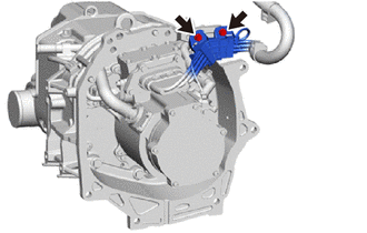
REMOVE FC AIR COMPRESSOR CABLE BRACKET
-
Disengage the clamp to separate the FC air compressor cable from the FC air compressor cable bracket.
-
Remove the bolt to separate the grounding wire from the FC air compressor cable bracket.
-
Remove the bolt and FC air compressor cable bracket from the FCV transaxle with motor assembly.
-
-
REMOVE FC AIR COMPRESSOR WITH MOTOR ASSEMBLY
-
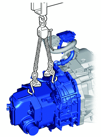
Using an engine sling device, support the FC air compressor with motor assembly.
Note
Set the engine sling device so that the FC air compressor with motor assembly is horizontal and level.
-
Attachment Placement Positions To enable the FC air compressor with motor assembly to be removed, change the position of the height adjustment attachment, and support the FCV transaxle with motor assembly.
Note
Using the height adjustment attachment, set the FC air compressor with motor assembly and FCV transaxle with motor assembly so that they are horizontal and level.
-
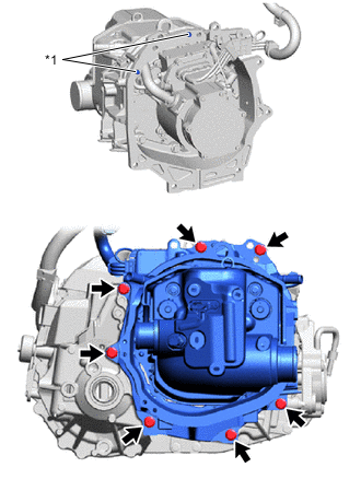
*1 Knock Pin Remove the 7 bolts.
-
Disengage the 2 knock pins to remove the FC air compressor with motor assembly from the FCV transaxle with motor assembly.
Note
Because the motor portion of the FC air compressor with motor assembly is inside the housing of the FCV transaxle with motor assembly, remove the FC air compressor with motor assembly without allowing the motor to contact the housing.
-
-
REMOVE FC AIR COMPRESSOR BRACKET
-
Remove the 2 bolts to separate the FC air compressor cable from the FC air compressor bracket.
-
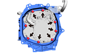
Remove the 8 bolts and FC air compressor bracket from the FC air compressor with motor assembly.
-