REGULATOR ASSEMBLY INSTALLATION

PROCEDURE
-
TEMPORARILY TIGHTEN HYDROGEN SUPPLY REGULATOR ASSEMBLY
Note
To prevent damage to seal portions or threaded portions, and to prevent openings from being contaminated by dust, metal fragments, etc., do not remove the protective caps of piping connection areas included with new parts until immediately before performing the procedure.
-
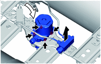

Lift Upwards 
Set While slightly lifting up the hydrogen tank tube joint supply bracket, set the hydrogen supply regulator assembly to the hydrogen tank frame FR CTR.
Note
Do not damage or deform the No. 4 hydrogen tank tube or the No. 5 hydrogen tank tube.
-
Temporarily tighten the hydrogen supply regulator assembly to the front center hydrogen tank frame.
-
-
TEMPORARILY TIGHTEN HYDROGEN TANK TUBE JOINT SUPPLY BRACKET
-
Temporarily tighten the hydrogen tank tube joint supply bracket to the front center hydrogen tank frame.
-
-
TEMPORARILY TIGHTEN NO. 6 HYDROGEN TANK TUBE
Note
To prevent damage to seal portions or threaded portions, and to prevent openings from being contaminated by dust, metal fragments, etc., do not remove the protective tape from the seal portions, threaded portions, and openings of the No. 1 hydrogen tank assembly and hydrogen tank tube joint until immediately before performing the procedure.
-
To prevent damage to seal portions or threaded portions, and to prevent openings from being contaminated by dust, metal fragments, etc., do not remove the protective tape from the seal portions, threaded portions, and openings of the hydrogen tank tube joint until immediately before performing the procedure.
-
To prevent damage to the seal portions and threaded portions, and to prevent foreign matter such as dust or metal fragments from entering the openings, do not remove the protective caps of the new hydrogen supply regulator assembly until immediately before performing work.
-
Temporarily tighten the No. 6 hydrogen tank tube to the hydrogen tank tube joint and hydrogen supply regulator assembly.
-
-
FULLY TIGHTEN HYDROGEN SUPPLY REGULATOR ASSEMBLY
-
Fully tighten the 4 installation bolts of the hydrogen supply regulator assembly.
- Torque:
- 13 N*m { 133 kgf*cm, 10 ft.*lbf }
-
-
FULLY TIGHTEN HYDROGEN TANK TUBE JOINT SUPPLY BRACKET
-
Fully tighten the 2 installation bolts of the hydrogen tank tube joint supply bracket.
- Torque:
- 13 N*m { 133 kgf*cm, 10 ft.*lbf }
-
-
FULLY TIGHTEN NO. 6 HYDROGEN TANK TUBE
-
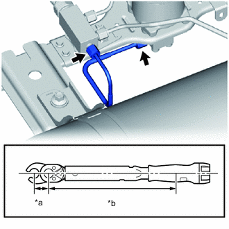
*a 17 mm Union Nut Wrench Fulcrum Length *b Torque Wrench Fulcrum Length Using a 17 mm union nut wrench, fully tighten the 2 union nuts.
- Torque:
- Specified tightening torque
- 25 N*m { 255 kgf*cm, 18 ft.*lbf }
Note
To prevent the tube from turning together, hold the tube in place while tightening the union nut.
Tech Tips
-
Calculate the torque wrench reading when changing the fulcrum length of the torque wrench.
-
When using 17 mm union nut wrench (fulcrum length of 30 mm (1.18 in.)) + torque wrench (fulcrum length of 255 mm (10.0 in.)):
22 N*m (224 kgf*cm, 16 ft.*lbf)
-
-
INSTALL NO. 2 HYDROGEN SUPPLY TUBE SUB-ASSEMBLY
-
INSTALL HYDROGEN TANK UNIT
-
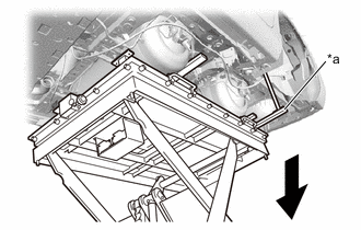
While shifting the hydrogen inlet receptacle assembly approximately 25 mm to the vehicle inner side, operate the engine lifter and slowly install the hydrogen tank unit to the vehicle.
Note
-
Do not apply excessive force to the high pressure hydrogen piping.
-
Make sure the hydrogen tank assembly and high pressure hydrogen piping do not interfere with the vehicle body or surrounding components.
-
-
Temporarily tighten the hydrogen tank unit to the vehicle with the 8 bolts.
-
Fully tighten the 8 bolts.
- Torque:
- 85 N*m { 867 kgf*cm, 63 ft.*lbf }
-
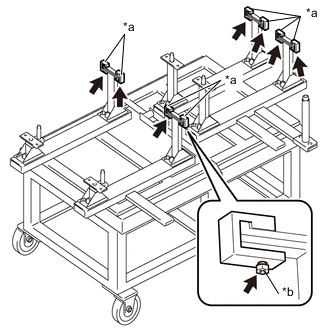
*a SST (Tank Belt Fixture) *b SST (Bolt) Remove the SST (bolts) and each SST (tank belt fixture).
- SST
- 09403-62010 ( 09403-06100, 09403-06110 )
-
*a SST (Hydrogen Tank Stand) Remove the SST (hydrogen tank stand).
- SST
- 09403-62010
-
-
CONNECT HYDROGEN INLET RECEPTACLE BRACKET SUB-ASSEMBLY
-
Temporarily tighten the hydrogen inlet receptacle bracket sub-assembly to the vehicle with the 5 bolts.
-
Fully tighten the 5 bolts.
- Torque:
- 13 N*m { 133 kgf*cm, 10 ft.*lbf }
-
Connect the hydrogen fuel control transmitter connector.
-
Engage the clamp and connect the wire harness clamp to the hydrogen inlet receptacle bracket sub-assembly.
-
-
CONNECT HYDROGEN TANK TUBE ASSEMBLY
-
Connect the bracket of the hydrogen tank tube assembly to the vehicle with the bolt.
- Torque:
- 22 N*m { 224 kgf*cm, 16 ft.*lbf }
Note
When tightening the bolt, to prevent the high pressure hydrogen piping from rotating together and being strained, hold the bracket portion of the hydrogen tank tube assembly in place by hand while performing the procedure.
-
-
CONNECT HYDROGEN TANK TUBE CLAMP BRACKET
-
INSTALL WIRING HARNESS CLAMP BRACKET
-
CONNECT NO. 1 HYDROGEN SUPPLY TUBE SUB-ASSEMBLY
-
CONNECT NO. 2 HYDROGEN SUPPLY TUBE SUB-ASSEMBLY
-
CONNECT NO. 3 FLOOR WIRE
-
CONNECT CABLE FROM NEGATIVE AUXILIARY BATTERY TERMINAL
-
INSTALL LUGGAGE TRIM SERVICE HOLE COVER
-
FIRST LEAK CHECK
-
CONNECT NO. 3 PARKING BRAKE CABLE ASSEMBLY
-
CONNECT NO. 2 PARKING BRAKE CABLE ASSEMBLY
-
INSTALL REAR AXLE BEAM ASSEMBLY
-
INSTALL FUEL FILLER OPENING LID SUB-ASSEMBLY
-
INSTALL FUEL TANK FILLER PIPE SHIELD
-
INSTALL FUEL TANK CAP COVER
-
CONNECT HYDROGEN INLET RECEPTACLE CAP
-
Connect the hydrogen inlet receptacle cap to the hydrogen inlet receptacle assembly.
-
-
INSTALL FUEL LID WITH MOTOR LOCK ASSEMBLY
-
INSTALL LUGGAGE COMPARTMENT TRIM COVER ASSEMBLY LH
-
INSTALL ROPE HOOK
-
INSTALL REAR FLOOR FINISH PLATE
-
INSTALL FRONT LUGGAGE COMPARTMENT TRIM COVER
-
INSTALL NO. 2 LUGGAGE COMPARTMENT TRIM HOOK
-
INSTALL NO. 1 LUGGAGE COMPARTMENT LIGHT ASSEMBLY
-
INSTALL LUGGAGE COMPARTMENT FLOOR MAT
-
INSTALL REAR WHEEL HOUSE LINER LH
-
Install the rear wheel house liner LH to the vehicle with the 12 clips.
-
Using a 4 mm socket hexagon wrench, install the hexagon screw.
-
-
INSTALL REAR BUMPER SIDE SEAL LH
-
INSTALL REAR WHEEL HOUSE FRONT PLATE LH
-
Install the rear wheel house front plate LH to the vehicle with the screw and 2 clips.
-
-
INSTALL NO. 2 FC EXHAUST PIPE
-
INSTALL NO. 3 FC EXHAUST PIPE
-
INSTALL FC EXHAUST TAIL PIPE ASSEMBLY
-
SECOND LEAK CHECK
-
INSTALL NO. 1 FLOOR UNDER COVER
-
INSTALL NO. 2 FLOOR UNDER COVER
-
INSTALL FRONT FLOOR CENTER COVER RH
-
INSTALL FRONT FLOOR CENTER COVER LH
-
INSTALL FRONT FLOOR COVER RH
-
INSTALL FRONT FLOOR COVER LH
-
INSTALL NO. 2 MOTOR UNDER COVER