RECEPTACLE ASSEMBLY INSTALLATION
PROCEDURE
-
INSTALL NO. 1 HYDROGEN INLET RECEPTACLE BRACKET CUSHION
Tech Tips
This procedure is only performed when the No. 1 hydrogen inlet receptacle bracket cushion is being replaced with a new one.
-
Clean and degrease the installation surface for the No. 1 hydrogen inlet receptacle bracket cushion on the hydrogen inlet receptacle bracket sub-assembly.
-
Separate a new No. 1 hydrogen inlet receptacle bracket cushion from its backing paper, making sure not to touch the adhesive surface.
-
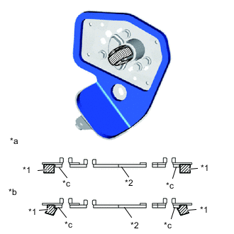
*1 No.1 Hydrogen Inlet Receptacle Bracket Cushion *2 Hydrogen Inlet Receptacle Bracket Sub-assembly *a Correct *b Incorrect *c A portion Install the No. 1 hydrogen inlet receptacle bracket cushion to the hydrogen inlet receptacle bracket sub-assembly as shown in the illustration.
Note
Make sure the No. 1 hydrogen inlet receptacle bracket cushion does not ride up on the A portion of the hydrogen inlet receptacle bracket sub-assembly.
-
-
INSTALL HYDROGEN INLET RECEPTACLE ASSEMBLY
Note
To prevent damage to seal portions or threaded portions, and to prevent openings from being contaminated by dust, metal fragments, etc., do not remove the protective caps of piping connection areas included with new parts until immediately before performing the procedure.
-
Temporarily tighten the hydrogen inlet receptacle assembly to the hydrogen inlet receptacle bracket sub-assembly with the 3 bolts.
-
Fully tighten the 3 bolts.
- Torque:
- 13 N*m { 133 kgf*cm, 10 ft.*lbf }
-
-
INSTALL HYDROGEN INLET RECEPTACLE BRACKET SUB-ASSEMBLY
-
Temporarily tighten the hydrogen inlet receptacle bracket sub-assembly to the vehicle with the 5 bolts.
-
Fully tighten the 5 bolts.
- Torque:
- 13 N*m { 133 kgf*cm, 10 ft.*lbf }
-
Connect the hydrogen fuel control transmitter connector.
-
Engage the clamp and connect the wire harness clamp to the hydrogen inlet receptacle bracket sub-assembly.
-
-
TEMPORARILY TIGHTEN HYDROGEN TANK TUBE ASSEMBLY
-
INSTALL FUEL TUBE GROMMET
-
INSTALL NO. 1 FUEL TUBE CLAMP
-
INSTALL HYDROGEN TANK TUBE CLAMP BRACKET
-
FULLY TIGHTEN HYDROGEN TANK TUBE ASSEMBLY
-
INSTALL WIRE HARNESS CLAMP
-
INSTALL HYDROGEN TANK UNIT