HYDROGEN TANK ASSEMBLY ON-VEHICLE INSPECTION

PROCEDURE
-
INSPECT HYDROGEN TANK ASSEMBLY FOR HYDROGEN GAS LEAK
-
Remove the front floor center cover LH.
-
Remove the front floor center cover RH.
-
Remove the No. 2 floor under cover.
-
Remove the No. 1 floor under cover.
-
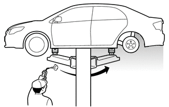
Blow compressed air around the underside of the vehicle.
Tech Tips
To enable accurate detection of hydrogen gas leaks from the piping, blow compressed air from the front of the vehicle towards the rear.
-
If there are water droplets, etc. adhering to any of the measurement locations, wipe them away before performing the procedures.
Note
If measurements are performed while water droplets, etc. are adhered, the hydrogen gas detector may be damaged.
-
Using SST and a hydrogen gas detector, measure each of the measurement locations for approximately 10 continuous seconds per location.
- SST
- 09401-62010
Note
-
Figure 1. <Hydrogen Gas Detector Contact Location>
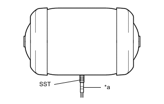
*a Hydrogen Gas Detector To perform the measurement, hold the tip of the hydrogen gas detector as shown in the illustration.
-
Hold the tip in light contact with the location so that the tip does not deform.
Tech Tips
Immediately after the measurement starts, the measured value may be unstable.
Figure 2. <Measurement Locations>
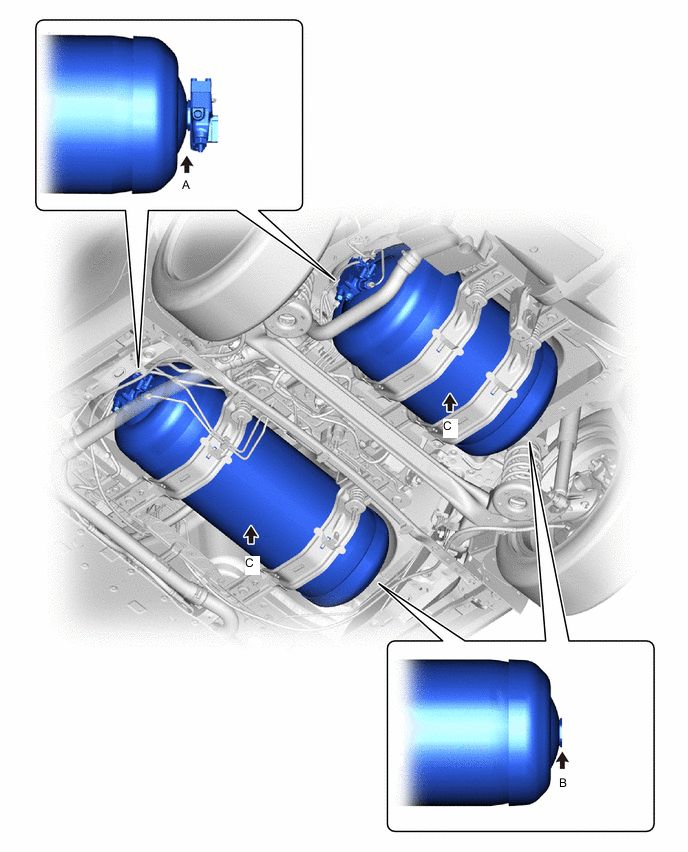
Illustration Item Measurement Location Measurement Method Specified Value A Boss Valve Side of Hydrogen Tank Assembly Measure the area near the boss or center of Hydrogen Tank Assembly. 300 ppm or less B Boss End Side of Hydrogen Tank Assembly C Center of Hydrogen Tank Assembly
(1 location in center of hydrogen tank assembly from underside of vehicle)
If the specification is not met, replace the hydrogen tank assembly with a new one.
-
Install the No. 1 floor under cover.
-
Install the No. 2 floor under cover.
-
Install the front floor center cover RH.
-
Install the front floor center cover LH.
-
-
INSPECT HYDROGEN TANK ASSEMBLY
-
Remove the front floor center cover LH.
-
Remove the front floor center cover RH.
-
Remove the No. 2 floor under cover.
-
Remove the No. 1 floor under cover.
-
Check that the hydrogen tank assembly is not damaged.
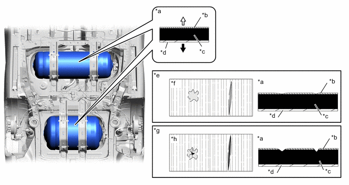
*a Hydrogen Tank Assembly Cutaway View *b GFRP (Glass Fiber Reinforced Plastic) Layer *c CFRP (Carbon Fiber Reinforced Plastic) Layer (Black) *d Resin Liner *e Pass *f CFRP (Carbon Fiber Reinforced Plastic) Layer (Black) is not exposed *g Reject *h CFRP (Carbon Fiber Reinforced Plastic) Layer (Black) is exposed 
Hydrogen Tank Assembly Inner Side 
Hydrogen Tank Assembly Outer Side OK The CFRP (Carbon Fiber Reinforced Plastic) Layer (Black) must not be exposed. Tech Tips
If the specification is not met, replace the hydrogen tank assembly with a new one.
-
Install the No. 1 floor under cover.
-
Install the No. 2 floor under cover.
-
Install the front floor center cover RH.
-
Install the front floor center cover LH.
-
-
INSPECT TANK SHUT VALVE PRESSURE RELIEF DEVISE
-
Remove the front floor center cover LH.
-
Remove the front floor center cover RH.
-
Remove the No. 2 floor under cover.
-
Remove the No. 1 floor under cover.
-
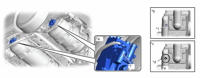
Check that the pressure relief device pin of the hydrogen tank assembly valve portion is not broken.
Tech Tips
-
The pressure relief device is a safety feature of the hydrogen tank assembly. If the vehicle is on fire, the metal inside the pressure relief device will melt and release the hydrogen gas, preventing the hydrogen tank assembly from bursting.
-
If the pressure relief device pin is broken and missing, the internal components of the pressure relief device cannot be held, and the hydrogen gas inside the hydrogen tank assembly may be released through the discharge hole.
*1 Pressure Relief Device - - *a Hydrogen Tank Assembly Valve Portion *b Pass *c Reject *d Pressure Relief Device Pin is broken OK Pressure Relief Device Pin is not broken. Tech Tips
If the specification is not met, replace the hydrogen tank assembly with a new one.
-
-
Install the No. 1 floor under cover.
-
Install the No. 2 floor under cover.
-
Install the front floor center cover RH.
-
Install the front floor center cover LH.
-
-
INSPECT TANK SHUT VALVE DISCHARGE HOLE SEAL
-
Remove the front floor center cover LH.
-
Remove the front floor center cover RH.
-
Remove the No. 2 floor under cover.
-
Remove the No. 1 floor under cover.
-
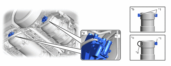
Check that the discharge hole seal of the hydrogen tank assembly is not peeled off.
Tech Tips
The discharge hole seal prevents foreign matter from entering the discharge hole (the hole through which hydrogen gas in the hydrogen tank assembly will be discharged if the pressure relief device activates).
*1 Discharge Hole Seal - - *a Hydrogen Tank Assembly Valve Portion *b Pass *c Reject *d Discharge Hole Seal is peeled off *e Discharge Hole - - OK Discharge Hole Seal is not peeled off. Tech Tips
If the specification is not met, use the following procedure to apply a new discharge hole seal.
-

*1 Discharge Hole Seal *a Guide *b Discharge Hole Clean and degrease the installation location of the discharge hole seal.
-
Using tweezers, etc., apply a new discharge hole seal along the guide.
Note
-
The discharge hole must not be visible.
-
The discharge hole seal must not be floating or separated from the surface.
-
-
-
Install the No. 1 floor under cover.
-
Install the No. 2 floor under cover.
-
Install the front floor center cover RH.
-
Install the front floor center cover LH.
-
-
INSPECT FOR HYDROGEN GAS LEAK
Note
Perform the hydrogen gas leak inspection when the fuel remaining warning light is not illuminated.
-
Remove the front floor center cover LH.
-
Remove the front floor center cover RH.
-
Remove the No. 2 floor under cover.
-
Remove the No. 1 floor under cover.
-
Remove the rear tire LH.
-
Remove the rear bumper side seal LH.
-
Peel back the rear wheel house liner LH.
-
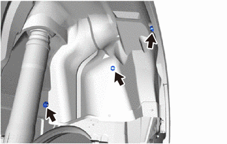
Remove the 3 clips.
-
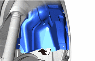
Peel Back As shown in the illustration, peel back the rear wheel house liner LH.
-
-
Blow compressed air around the underside of the vehicle.
Tech Tips
To enable accurate detection of hydrogen gas leaks from the piping, blow compressed air from the front of the vehicle towards the rear.
-
If there are water droplets, etc. adhering to any of the measurement locations, wipe them away before performing the procedures.
Note
If measurements are performed while water droplets, etc. are adhered, the hydrogen gas detector may be damaged.
-
Using SST and a hydrogen gas detector, measure each of the measurement locations for approximately 10 continuous seconds per location.
- SST
- 09401-62010
Tech Tips
-
Immediately after the measurement starts, the measured value may be unstable.
-
If the measured value is outside of the specification, remove the hydrogen tank unit from the vehicle and replace the leaking component with a new one.
Figure 4. <Measurement Locations>
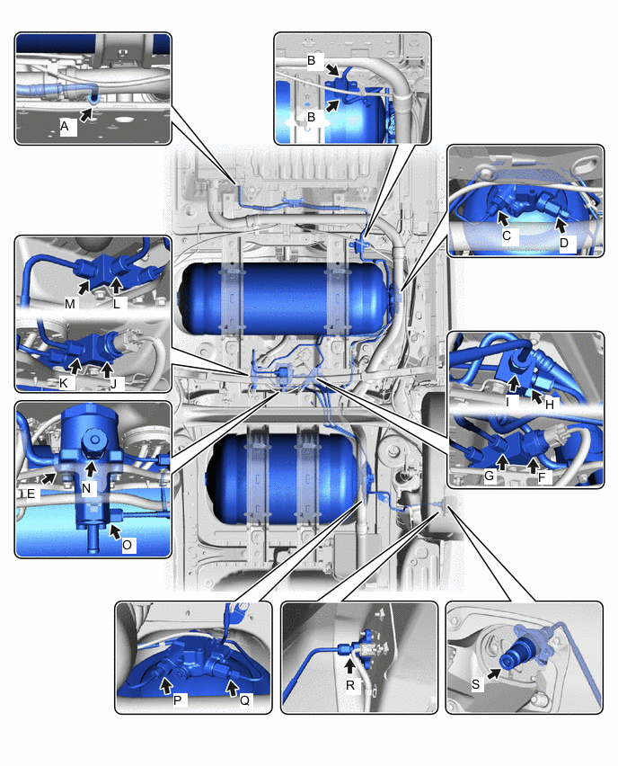
Measurement Location and Direction - - Illustration Item Measurement Location Measurement Method Specified Value A Connection between FC Stack Assembly and No. 1 Hydrogen Supply Tube Sub-assembly Measure the area near the piping, connecting portion, or sensor connecting portion. 300 ppm or less B Connection between No. 1 Hydrogen Supply Tube Sub-assembly and No. 2 Hydrogen Supply Tube Sub-assembly C Connection between No. 1 Hydrogen Tank Assembly and No. 4 Hydrogen Tank Tube D Connection between No. 1 Hydrogen Tank Assembly and No. 2 Hydrogen Tank Tube E Connection between Hydrogen Supply Regulator Assembly and No. 2 Hydrogen Supply Tube Sub-assembly F Hydrogen Tank Tube Joint (for Inlet Side), installation location of Hydrogen Tank Pressure Sensor G Connection between Hydrogen Tank Tube Joint (for Inlet Side) and No. 3 Hydrogen Tank Tube H Connection between Hydrogen Tank Tube Joint (for Inlet Side) and Hydrogen Tank Tube Assembly I Connection between Hydrogen Tank Tube Joint (for Inlet Side) and No. 2 Hydrogen Tank Tube J Hydrogen Tank Tube Joint (for Outlet Side), installation location of Hydrogen Tank Pressure Sensor K Connection between Hydrogen Tank Tube Joint (for Outlet Side) and No. 5 Hydrogen Tank Tube L Connection between Hydrogen Tank Tube Joint (for Outlet Side) and No. 4 Hydrogen Tank Tube M Connection between Hydrogen Tank Tube Joint (for Outlet Side) and No. 6 Hydrogen Tank Tube N Medium Pressure Port of Hydrogen Supply Regulator Assembly
*1
O Connection between Hydrogen Supply Regulator Assembly and No. 6 Hydrogen Tank Tube P Connection between No. 2 Hydrogen Tank Assembly and No. 5 Hydrogen Tank Tube Q Connection between No. 2 Hydrogen Tank Assembly and No. 3 Hydrogen Tank Tube R Connection between Hydrogen Inlet Receptacle Assembly and Hydrogen Tank Tube Assembly
*2
S Filling Port of Hydrogen Inlet Receptacle Assembly
*3
Perform measurement with the tip of the hydrogen leak detector in direct contact with the filling port.
*4, *5
1000 ppm or less
-
*1: If the value is not as specified, replace the O-ring of the medium pressure port.
-
*2: Measure from underneath the vehicle, with the rear wheel house liner LH peeled back.
-
*3: Because there is a possibility of erroneously detecting hydrogen that has accumulated near the filling port, open the hydrogen inlet receptacle cap and wait for at least 3 minutes before performing the measurement.
-
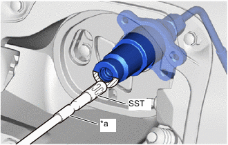
*a Hydrogen Leak Detector 
Contact Area for Hydrogen Leak Detector *4: When performing leak inspection of the hydrogen inlet receptacle assembly, hold the tip of the hydrogen leak detector in light contact with the area shown in the illustration.
-
*5: To prevent damage to the O-ring, do not insert the tip of the hydrogen leak detector into the filling port of the hydrogen inlet receptacle assembly.
-
Connect the hydrogen inlet receptacle cap, and close the fuel lid.
-
Install the rear wheel house liner LH.
-
Return the rear wheel house liner LH to its original position and secure it with the 3 clips.
-
-
Install the rear bumper side seal LH.
-
Install the rear tire LH.
-
Install the No. 1 floor under cover.
-
Install the No. 2 floor under cover.
-
Install the front floor center cover RH.
-
Install the front floor center cover LH.
-