PRESSURE SENSOR REMOVAL
CAUTION / NOTICE / HINT
The necessary procedures (adjustment, calibration, initialization, or registration) that must be performed after parts are removed, installed, or replaced during the turbo pressure sensor removal/installation are shown below.
| Replacement Part or Procedure | Necessary Procedure | Effects/Inoperative when not Performed | Link |
|---|---|---|---|
| Front wheel alignment adjustment |
|
VSC malfunctions | |
| Adjust lane departure warning camera | Lane departure alert system malfunctions |
CAUTION:
-
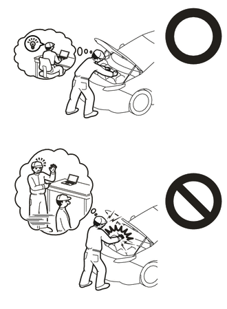
This vehicle contains high voltage circuits standardized with orange colored wiring and connectors, so follow the instructions in this manual to perform the procedures correctly.
-
If the correct procedures are not followed according to the instructions in this manual, there is a danger of electric shock from the high voltage circuits.
-
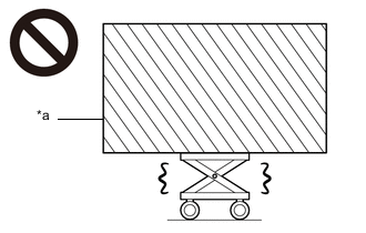
*a Heavy object exceeding the capacity of the engine lifter Because the weight of the FCV transaxle with FC air compressor assembly is extremely heavy, make sure to follow the work procedures described in the repair manual.
-
If work is not performed according to the procedures described in the repair manual, there is a danger that the engine lifter could drop and components could fall down.
-

Be sure to wear insulating gloves when working on high voltage wiring or components.
-
If work is performed without wearing insulating gloves, there is a danger of electric shock.
Note
When the vehicle is parked with the power switch off, if the FC control ECU judges that the FC stack temperature will go below 0°C (32°F), it activates the FC air compressor, hydrogen pump and FC cooling water pump for a maximum of 180 seconds and drains water from the FC stack assembly. When performing inspection or repairs with the power switch off (not on (IG) or on (READY)), disconnect the cable from the negative (-) auxiliary battery terminal before performing work.
PROCEDURE
-
CAUTIONS FOR HIGH VOLTAGE SYSTEM COMPONENTS
-
CAUTIONS FOR COOLANT (FC STACK COOLANT)
-
CAUTIONS FOR INTAKE SYSTEM COMPONENTS
-
REMOVE FC AIR COMPRESSOR WITH MOTOR ASSEMBLY
-
REMOVE FC AIR COMPRESSOR LOWER COVER
-
REMOVE TURBO PRESSURE SENSOR
-
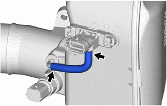
Remove the vacuum hose.
Note
Do not allow any foreign matter to enter the vacuum hose or port.
-
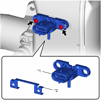
*1 Turbo Pressure Sensor *2 FC Air Compressor Pressure Sensor Stay Remove the 2 screws, turbo pressure sensor and FC air compressor pressure sensor stay from the FC air compressor with motor assembly.
Note
If the turbo pressure sensor is dropped or subjected to a strong impact, replace it with a new one.
-