FC INVERTER INPUT JUNCTION ASSEMBLY INSTALLATION
PROCEDURE
-
INSTALL HIGH VOLTAGE FUSE
Note
Do not allow foreign matter or water droplets to enter the FC inverter input junction assembly.
Tech Tips
Perform this procedure when the high voltage fuse must be replaced.
-
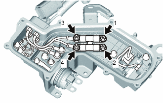
Temporarily install the 2 high voltage fuses to the FC inverter input junction assembly with 4 new nuts.
-
Tighten the 4 nuts in the order shown in the illustration.
- Torque:
- 4.5 N*m { 46 kgf*cm, 40 in.*lbf }
-
Remove all of the old seal packing remaining on the sealing surface between the junction block service cover and FC inverter input junction assembly, and using non-residue solvent, clean and degrease the sealing surface.
Note
Do not scratch or damage the sealing surface between the junction block service cover and FC inverter input junction assembly.
-
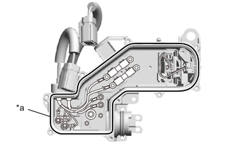
*a Seal Packing 1282B Using Seal Packing 1282B or equivalent, apply an unbroken bead 2.0 to 4.0 mm in diameter to the FC inverter input junction assembly in the location shown in the illustration.
Seal Packing Toyota Genuine Seal Packing 1282B, Three Bond 1282B or equivalent Note
After applying the Seal Packing 1282B or equivalent, install the junction block service cover within 3 minutes, and tighten the bolts within 15 minutes.
-
Install the junction block service cover to the FC inverter input junction assembly with the 9 bolts.
- Torque:
- 5.5 N*m { 56 kgf*cm, 49 in.*lbf }
-
-
INSTALL PACKING SEAL
Tech Tips
Perform this procedure when the packing seal must be replaced.
-
Install the packing seal to the FC inverter input junction assembly.
-
-
REMOVE INVERTER TERMINAL COVER
-
INSTALL FC INVERTER INPUT JUNCTION ASSEMBLY
CAUTION:
Wear insulated gloves.
Note
Do not allow foreign matter or water droplets to enter the inverter with converter assembly.
-
To prevent contamination by foreign matter or water droplets, remove the protective tape from the opening of the inverter with converter assembly immediately before performing the procedure.
-
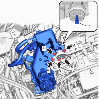
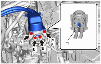
*1 Interlock Connector Temporarily install the FC inverter input junction assembly to the inverter with converter assembly with the 5 bolts.
Note
-
To prevent damage to the threaded portion, be sure to perform the work by hand.
-
If the packing seal of the FC inverter input junction assembly has any damage or deformation, replace it with a new one.
-
Do not touch the packing seal or terminal portion of the FC inverter input junction assembly.
-
When installing, do not damage or scratch the terminal portions, connector housing, or inverter with converter assembly.
-
Securely connect the interlock connector.
HINT Item Bolt Head Shape Bolt A Flange Bolt Bolt B Bolt with Washer -
-
Using an insulated tool, tighten the 3 bolts A.
- Torque:
- 8.0 N*m { 82 kgf*cm, 71 in.*lbf }
-
Using an insulated tool, tighten the 2 bolts B.
- Torque:
- 8.0 N*m { 82 kgf*cm, 71 in.*lbf }
-
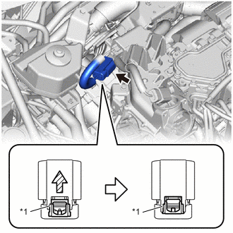
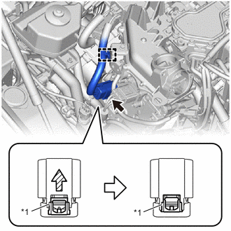
*1 Green-colored Lock Connect the connector to the electric heater sub-assembly and press in the green lock to securely fix the connector in place as shown in the illustration.
Note
-
Do not touch the connector terminals.
-
Check that the connector is securely connected.
-
-
*1 Green-colored Lock Connect the connector to the FC water and hydrogen pump inverter assembly and press in the green lock to securely fix the connector in place as shown in the illustration.
Note
-
Do not touch the connector terminals.
-
Check that the connector is securely connected.
-
-
Engage the clamp to connect the wire harness to the FC inverter input junction assembly.
-
-
INSTALL INVERTER TERMINAL COVER
-
CONNECT FRAME WIRE
CAUTION:
Wear insulated gloves.
-
To prevent contamination by foreign matter or water droplets, remove the protective tape from the openings of the FC inverter input junction assembly immediately before performing the procedure.
-
*1 Interlock Connector Temporarily install the frame wire to the FC inverter input junction assembly with the 4 bolts.
Note
-
To prevent damage to the threaded portion, be sure to perform the work by hand.
-
Do not touch the rubber seal or terminal portion of the frame wire.
-
When connecting, do not damage or scratch the terminal portions, connector housing, or FC inverter input junction assembly.
-
Securely connect the interlock connector.
HINT Item Bolt Head Shape Bolt A Flange Bolt Bolt B Bolt with Washer -
-
Using an insulated tool, tighten the 2 bolts A.
- Torque:
- 8.0 N*m { 82 kgf*cm, 71 in.*lbf }
-
Using an insulated tool, tighten the 2 bolts B.
- Torque:
- 8.0 N*m { 82 kgf*cm, 71 in.*lbf }
-
-
INSTALL FC INVERTER INPUT JUNCTION COVER
CAUTION:
Wear insulated gloves.
-
Install the FC inverter input junction cover to the FC inverter input junction assembly with the 2 bolts.
- Torque:
- 8.0 N*m { 82 kgf*cm, 71 in.*lbf }
Note
-
Do not touch the rubber seal of the FC inverter input junction cover.
-
Securely connect the interlock connector.
-
Engage the clamp to connect the wire harness from the FC inverter input junction cover.
-
Connect the FC inverter input junction cover connector.
-
-
INSTALL FC WATER PUMP DRAIN HOSE ASSEMBLY
-
Install the FC water pump drain hose assembly to the FC inverter input junction assembly with the bolt.
- Torque:
- 13 N*m { 133 kgf*cm, 10 ft.*lbf }
-
-
INSTALL INVERTER COVER
-
INSTALL AIR CLEANER SUPPORT
-
Install the air cleaner support to the FC inverter input junction assembly.
-
-
INSTALL AIR CLEANER WITH ELEMENT ASSEMBLY
-
INSTALL AIR CLEANER INLET
-
INSTALL COOL AIR INTAKE DUCT SEAL
-
INSTALL OUTER COWL TOP PANEL SUB-ASSEMBLY (for LHD)
-
INSTALL OUTER COWL TOP PANEL SUB-ASSEMBLY (for RHD)
-
INSTALL COWL BODY MOUNTING REINFORCEMENT RH (for LHD)
-
INSTALL COWL BODY MOUNTING REINFORCEMENT RH (for RHD)
-
INSTALL WATER GUARD PLATE LH (for LHD)
-
INSTALL WATER GUARD PLATE RH (for RHD)
-
INSTALL NO. 2 HEATER AIR DUCT SPLASH SHIELD SEAL (for LHD)
-
INSTALL NO. 1 HEATER AIR DUCT SPLASH SHIELD SEAL (for RHD)
-
INSTALL WINDSHIELD WIPER MOTOR AND LINK
-
INSTALL FC STACK SERVICE PLUG GRIP
-
INSTALL SERVICE PLUG GRIP (for EV)