FC INVERTER INPUT JUNCTION ASSEMBLY REMOVAL
CAUTION / NOTICE / HINT
CAUTION:
-
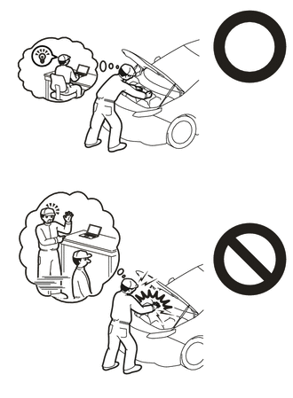
This vehicle contains high voltage circuits standardized with orange colored wiring and connectors, so follow the instructions in this manual to perform the procedures correctly.
-
If the correct procedures are not followed according to the instructions in this manual, there is a danger of electric shock from the high voltage circuits.
-

Be sure to wear insulating gloves when working on high voltage wiring or components.
-
If work is performed without wearing insulating gloves, there is a danger of electric shock.
PROCEDURE
-
CAUTIONS FOR HIGH VOLTAGE SYSTEM COMPONENTS
-
CAUTIONS FOR INTAKE SYSTEM COMPONENTS
-
REMOVE SERVICE PLUG GRIP (for EV)
-
REMOVE FC STACK SERVICE PLUG GRIP
-
REMOVE WINDSHIELD WIPER MOTOR AND LINK
-
REMOVE NO. 2 HEATER AIR DUCT SPLASH SHIELD SEAL (for LHD)
-
REMOVE NO. 1 HEATER AIR DUCT SPLASH SHIELD SEAL (for RHD)
-
REMOVE WATER GUARD PLATE LH (for LHD)
-
REMOVE WATER GUARD PLATE RH (for RHD)
-
REMOVE COWL BODY MOUNTING REINFORCEMENT RH (for LHD)
-
REMOVE COWL BODY MOUNTING REINFORCEMENT RH (for RHD)
-
REMOVE OUTER COWL TOP PANEL SUB-ASSEMBLY (for LHD)
-
REMOVE OUTER COWL TOP PANEL SUB-ASSEMBLY (for RHD)
-
REMOVE COOL AIR INTAKE DUCT SEAL
-
REMOVE AIR CLEANER INLET
-
REMOVE AIR CLEANER WITH ELEMENT ASSEMBLY
-
REMOVE AIR CLEANER SUPPORT
-
Remove the air cleaner support from the FC inverter input junction assembly.
-
-
REMOVE INVERTER COVER
-
REMOVE INVERTER TERMINAL COVER
-
CHECK TERMINAL VOLTAGE
-
TEMPORARILY TIGHTEN INVERTER TERMINAL COVER
-
SEPARATE FC WATER PUMP DRAIN HOSE ASSEMBLY
-
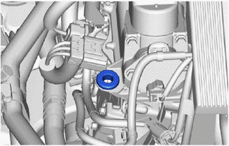
Remove the bolt and FC water pump drain hose assembly from the FC inverter input junction assembly.
-
-
REMOVE FC INVERTER INPUT JUNCTION COVER
CAUTION:
Wear insulated gloves.
-
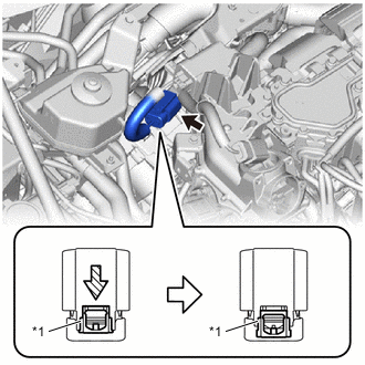
Disconnect the FC inverter input junction cover connector.
-
Disengage the clamp to separate the wire harness from the FC inverter input junction cover.
-
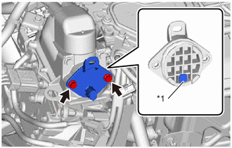
*1 Interlock Connector Remove the 2 bolts and FC inverter input junction cover from the FC inverter input junction assembly.
Note
-
Because the FC inverter input junction cover has an interlock connector, pull it straight out.
-
Do not touch the rubber seal of the FC inverter input junction cover.
-
-
-
DISCONNECT FRAME WIRE
CAUTION:
Wear insulated gloves.
-
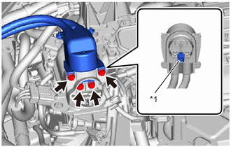
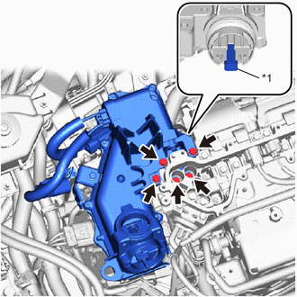
*1 Interlock Connector Using an insulated tool, remove the 4 bolts and disconnect the frame wire from the FC inverter input junction assembly.
Note
-
Because the frame wire has an interlock connector, pull it out straight.
-
When disconnecting, do not damage the terminal portion, connector housing, or FC inverter input junction assembly.
-
Do not touch the rubber seal or terminal portion of the frame wire.
-
Insulate the terminal portion of the frame wire by wrapping it with insulating tape.
-
-
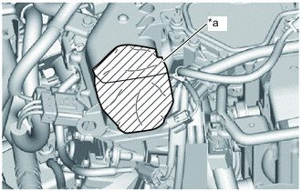
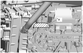
*a Protective Tape To prevent contamination by foreign matter or water droplets, cover the openings of the FC inverter input junction assembly with protective tape.
-
-
REMOVE INVERTER TERMINAL COVER
-
REMOVE FC INVERTER INPUT JUNCTION ASSEMBLY
CAUTION:
Wear insulated gloves.
Note
Do not allow foreign matter or water droplets to enter the inverter with converter assembly.
-
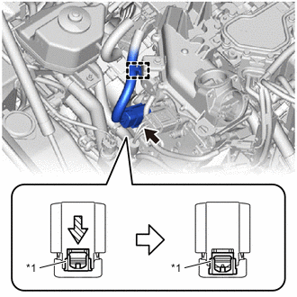
*1 Green-colored Lock Disengage the clamp to separate the wire harness from the FC inverter input junction assembly.
-
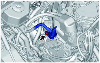
Pull out the green lock of the connector and disconnect the connector from the FC water and hydrogen pump inverter assembly as shown in the illustration.
Note
-
Do not touch the connector terminals.
-
Insulate the opening of the connector by wrapping it with insulating tape.
-
-
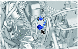
*1 Green-colored Lock Pull out the green lock of the connector and disconnect the connector from the electric heater sub-assembly as shown in the illustration.
Note
-
Do not touch the connector terminals.
-
Insulate the opening of the connector by wrapping it with insulating tape.
-
-
*1 Interlock Connector Using an insulated tool, remove the 5 bolts and FC inverter input junction assembly from the inverter with converter assembly.
Note
-
Because the FC inverter input junction assembly has an interlock connector, pull it straight out.
-
When removing, do not damage the terminal portion, connector housing or inverter with converter assembly.
-
Do not touch the seal packing or terminal portion of the FC inverter input junction assembly.
-
If the seal packing of the FC inverter input junction assembly has any damage or deformation, replace it with a new one.
-
Insulate the terminal portion of the FC inverter input junction assembly by wrapping it with insulating tape.
-
-
*a Protective Tape To prevent contamination by foreign matter or water droplets, cover the opening of the inverter with converter assembly with protective tape.
-
-
TEMPORARILY TIGHTEN INVERTER TERMINAL COVER
-
REMOVE PACKING SEAL
Tech Tips
Perform this procedure when the packing seal must be replaced.
-
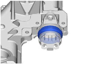
Remove the packing seal from the FC inverter input junction assembly.
-
-
REMOVE HIGH VOLTAGE FUSE
Note
Do not allow foreign matter or water droplets to enter the FC inverter input junction assembly.
Tech Tips
Perform this procedure when the high voltage fuse must be replaced.
-
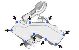
Remove the 9 bolts.
-
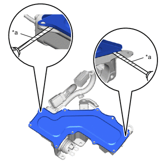
*a Protective Tape Using a screwdriver with its tip wrapped in protective tape, pry the 2 locations shown in the illustration and remove the junction block service cover from the FC inverter input junction assembly.
Note
-
Do not scratch or damage the sealing surface between the junction block service cover and FC inverter input junction assembly.
-
If the junction block service cover has any deformation, replace it with a new one.
-
-
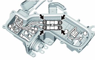
Remove the 4 nuts and 2 high voltage fuses from the FC inverter input junction assembly.
-