FC CONVERTER POWER OUTLET CABLE INSTALLATION
PROCEDURE
-
INSTALL FC CONVERTER POWER OUTLET CABLE
CAUTION:
Wear insulated gloves.
-
To prevent contamination by foreign matter or water droplets, remove the protective tape from the openings of the FC converter assembly immediately before performing the procedure.
-
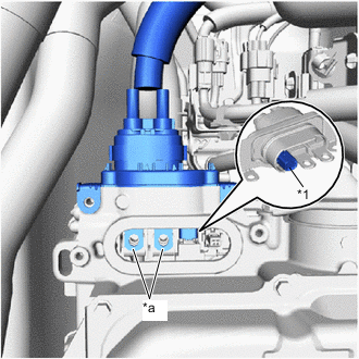
*1 Interlock Connector *a Terminal Portion Install the FC converter power outlet cable to the FC converter assembly.
Note
-
Do not touch the rubber seal or terminal portion of the FC converter power outlet cable.
-
Do not apply any impacts to the terminal portion of the FC converter power outlet cable.
-
Do not scratch or damage the FC converter assembly with the terminal portion of the FC converter power outlet cable.
-
Securely connect the interlock connector.
-
Check that the terminal of the FC converter power outlet cable can be seen from the installation area of the front FC converter service hole cover.
-
-
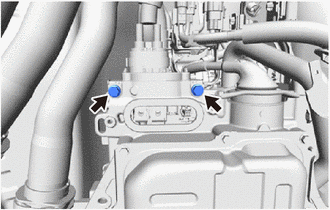
Using an insulated tool, install the 2 bolts.
- Torque:
- 8.0 N*m { 82 kgf*cm, 71 in.*lbf }
-
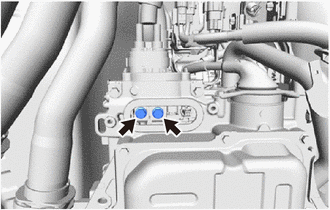
Using an insulated tool, install the 2 bolts.
- Torque:
- 8.0 N*m { 82 kgf*cm, 71 in.*lbf }
-
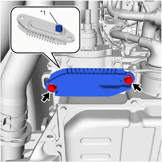
*1 Interlock Connector Install the front FC converter service hole cover to the FC converter assembly with the 2 bolts.
- Torque:
- 8.0 N*m { 82 kgf*cm, 71 in.*lbf }
Note
-
Do not allow foreign matter to adhere to the surface of the gasket of the front FC converter service hole cover.
-
Securely connect the interlock connector.
-
Make sure not to drop the gasket of the front FC converter service hole cover.
-
Engage the clamp to connect the FC converter power outlet cable to the FC stack cooling water outlet bracket.
-
Engage the clamp to connect the FC converter power outlet cable to the FC converter power outlet bracket.
-
-
INSTALL SUSPENSION MEMBER TO FRONT CROSSMEMBER BRACE SUB-ASSEMBLY
-
Install the suspension member to front crossmember brace sub-assembly to the vehicle with the 5 bolts.
- Torque:
- 79 N*m { 806 kgf*cm, 58 ft.*lbf }
-
-
INSTALL FRONT FLOOR COVER RH
-
INSTALL FRONT FLOOR COVER LH
-
INSTALL NO. 2 MOTOR UNDER COVER
-
CONNECT FC CONVERTER POWER OUTLET CABLE
CAUTION:
Wear insulated gloves.
-
Engage the clamp to connect the FC converter power outlet cable to the FC cooling water valve bracket.
-
-
INSTALL OUTER COWL TOP PANEL SUB-ASSEMBLY (for LHD)
-
INSTALL OUTER COWL TOP PANEL SUB-ASSEMBLY (for RHD)
-
INSTALL COWL BODY MOUNTING REINFORCEMENT RH (for LHD)
-
INSTALL COWL BODY MOUNTING REINFORCEMENT RH (for RHD)
-
INSTALL WATER GUARD PLATE LH (for LHD)
-
INSTALL WATER GUARD PLATE RH (for RHD)
-
INSTALL NO. 2 HEATER AIR DUCT SPLASH SHIELD SEAL (for LHD)
-
INSTALL NO. 1 HEATER AIR DUCT SPLASH SHIELD SEAL (for RHD)
-
INSTALL WINDSHIELD WIPER MOTOR AND LINK
-
INSTALL FC CONVERTER POWER OUTLET CABLE
CAUTION:
Wear insulated gloves.
Note
Do not allow foreign matter or water droplets to enter the inverter with converter assembly.
-
To prevent contamination by foreign matter or water droplets, remove the protective tape from the openings of the inverter with converter assembly immediately before performing the procedure.
-
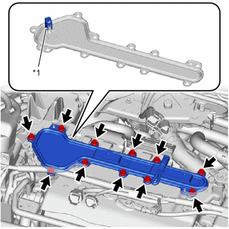
*1 Interlock Connector Remove the 11 bolts and inverter terminal cover from the inverter with converter assembly.
Note
-
The inverter terminal cover has an interlock connector, so pull it up vertically.
-
Do not touch the rubber seal of the inverter terminal cover.
-
-
Using an insulated tool, connect the FC converter power outlet cable to the inverter with converter assembly with the 2 bolts.
- Torque:
- 8.0 N*m { 82 kgf*cm, 71 in.*lbf }
Note
-
Do not touch the rubber seal or terminal portion of the FC converter power outlet cable.
-
Do not apply any impacts to the terminal portion of the FC converter power outlet cable.
-
Do not scratch or damage the inverter with converter assembly with the terminal portion of the FC converter power outlet cable.
-
Using an insulated tool, install the 3 bolts.
- Torque:
- 8.0 N*m { 82 kgf*cm, 71 in.*lbf }
-
-
INSTALL INVERTER TERMINAL COVER
CAUTION:
Wear insulated gloves.
-
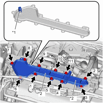
*1 Interlock Connector *2 Connector Bracket Temporarily install the inverter terminal cover to the inverter with converter assembly with the 11 bolts.
Note
-
Check that the rubber seal is installed to the inverter terminal cover, and install the inverter terminal cover to the inverter with converter assembly.
-
Do not touch the rubber seal of the inverter terminal cover.
-
Do not install the inverter terminal cover while pressing down on the connector bracket.
-
Securely connect the interlock connector.
-
-
Tighten the 11 bolts in the order shown in the illustration.
- Torque:
- 8.0 N*m { 82 kgf*cm, 71 in.*lbf }
-
Engage the 2 clamps to connect the wire harnesses to the inverter terminal cover.
-
Connect the 4 connectors.
-
-
INSTALL INVERTER COVER
-
INSTALL FC STACK SERVICE PLUG GRIP
-
INSTALL SERVICE PLUG GRIP (for EV)