FC CONVERTER POWER OUTLET CABLE REMOVAL
CAUTION / NOTICE / HINT
CAUTION:
-
This vehicle contains high voltage circuits standardized with orange colored wiring and connectors, so follow the instructions in this manual to perform the procedures correctly.
-
If the correct procedures are not followed according to the instructions in this manual, there is a danger of electric shock from the high voltage circuits.
-

Be sure to wear insulating gloves when working on high voltage wiring or components.
-
If work is performed without wearing insulating gloves, there is a danger of electric shock.
PROCEDURE
-
CAUTIONS FOR HIGH VOLTAGE SYSTEM COMPONENTS
-
REMOVE SERVICE PLUG GRIP (for EV)
-
REMOVE FC STACK SERVICE PLUG GRIP
-
REMOVE INVERTER COVER
-
REMOVE INVERTER TERMINAL COVER
CAUTION:
Wear insulated gloves.
Note
Do not allow foreign matter or water droplets to enter the inverter with converter assembly.
-
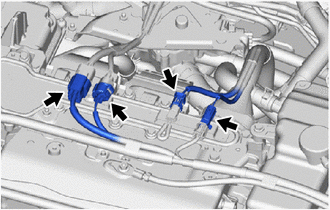
Disconnect the 4 connectors.
-
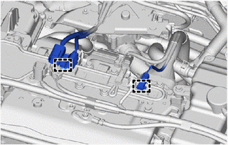
Disengage the 2 clamps to separate the wire harnesses from the inverter terminal cover.
-
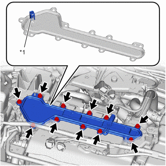
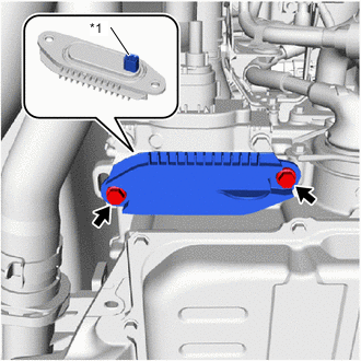
*1 Interlock Connector Remove the 11 bolts and inverter terminal cover from the inverter with converter assembly.
Note
-
The inverter terminal cover has an interlock connector, so pull it up vertically.
-
Do not touch the rubber seal of the inverter terminal cover.
-
-
-
CHECK TERMINAL VOLTAGE
-
DISCONNECT FC CONVERTER POWER OUTLET CABLE
CAUTION:
Wear insulated gloves.
Note
Do not allow foreign matter or water droplets to enter the inverter with converter assembly.
-
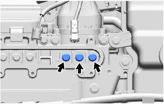
Using an insulated tool, remove the 3 bolts.
-
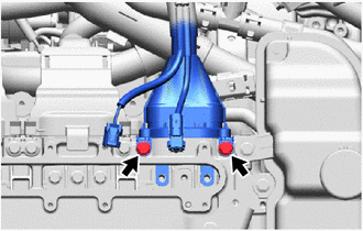
Using an insulated tool, remove the 2 bolts to disconnect the FC converter power outlet cable from the inverter with converter assembly.
Note
-
Do not touch the rubber seal or terminal portion of the FC converter power outlet cable.
-
Do not touch the rubber seal or terminal portion of the FC converter power outlet cable.
-
Do not scratch or damage the FC converter assembly with the terminal portion of the FC converter power outlet cable.
-
Insulate the terminal portion of the FC converter power outlet cable by wrapping it with insulating tape.
-
-
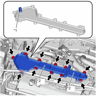
*1 Interlock Connector *2 Connector Bracket To prevent foreign matter or water droplets from entering the inverter with converter assembly, temporarily install the inverter terminal cover to the inverter with converter assembly with the 11 bolts.
Note
-
Check that the rubber seal is installed to the inverter terminal cover, and install the inverter terminal cover to the inverter with converter assembly.
-
Do not touch the rubber seal of the inverter terminal cover.
-
Do not install the inverter terminal cover while pressing down on the connector bracket.
-
Securely connect the interlock connector.
-
-
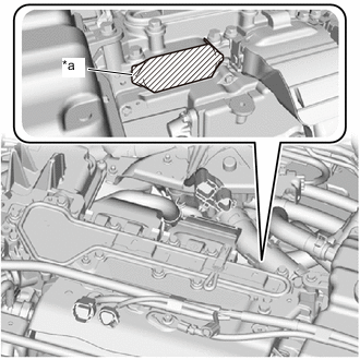
*a Protective Tape To prevent contamination by foreign matter or water droplets, cover the openings of the inverter with converter assembly with protective tape.
-
-
REMOVE WINDSHIELD WIPER MOTOR AND LINK
-
REMOVE NO. 2 HEATER AIR DUCT SPLASH SHIELD SEAL (for LHD)
-
REMOVE NO. 1 HEATER AIR DUCT SPLASH SHIELD SEAL (for RHD)
-
REMOVE WATER GUARD PLATE LH (for LHD)
-
REMOVE WATER GUARD PLATE RH (for RHD)
-
REMOVE COWL BODY MOUNTING REINFORCEMENT RH (for LHD)
-
REMOVE COWL BODY MOUNTING REINFORCEMENT RH (for RHD)
-
REMOVE OUTER COWL TOP PANEL SUB-ASSEMBLY (for LHD)
-
REMOVE OUTER COWL TOP PANEL SUB-ASSEMBLY (for RHD)
-
SEPARATE FC CONVERTER POWER OUTLET CABLE
CAUTION:
Wear insulated gloves.
-
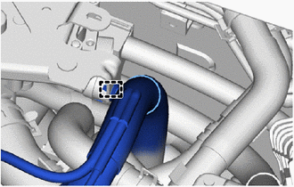
Disengage the clamp to separate the FC converter power outlet cable from the FC cooling water valve bracket.
-
-
REMOVE NO. 2 MOTOR UNDER COVER
-
REMOVE FRONT FLOOR COVER LH
-
REMOVE FRONT FLOOR COVER RH
-
REMOVE SUSPENSION MEMBER TO FRONT CROSSMEMBER BRACE SUB-ASSEMBLY
-
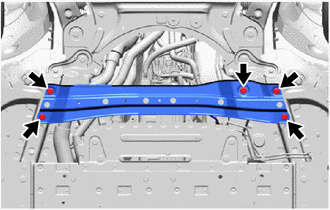
Remove the 5 bolts and suspension member to front crossmember brace sub-assembly from the vehicle.
-
-
REMOVE FC CONVERTER POWER OUTLET CABLE
CAUTION:
Wear insulated gloves.
-
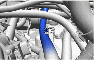
Disengage the clamp to separate the FC converter power outlet cable from the FC converter power outlet bracket.
-
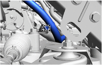
Disengage the clamp to separate the FC converter power outlet cable from the FC stack cooling water outlet bracket.
-
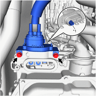
*1 Interlock Connector Remove the 2 bolts and front FC converter service hole cover from the FC converter assembly.
Note
-
The front FC converter service hole cover has an interlock connector, so pull it down straight.
-
Make sure not to drop the gasket of the front FC converter service hole cover.
-
-
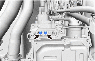
Using an insulated tool, remove the 2 bolts.
-
*1 Interlock Connector Using an insulated tool, remove the 2 bolts and FC converter power outlet cable from the FC converter assembly.
Note
-
The FC converter power outlet cable has an interlock connector, so pull it out straight.
-
Do not touch the rubber seal or terminal portion of the FC converter power outlet cable.
-
Do not apply any impacts to the terminal portion of the FC converter power outlet cable.
-
Do not scratch or damage the FC converter assembly with the terminal portion of the FC converter power outlet cable.
-
Insulate the terminal portion of the FC converter power outlet cable by wrapping it with insulating tape.
-
-
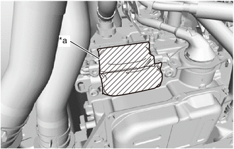
*a Protective Tape To prevent contamination by foreign matter or water droplets, cover the openings of the FC converter assembly with protective tape.
-