PRESSURE SENSOR INSTALLATION
PROCEDURE
-
INSTALL HYDROGEN TANK PRESSURE SENSOR
-
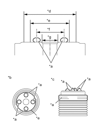
*a TOYOTA Genuine FC Grease (Applied to Seal Inner Surface) *b Upper View *c Side View *d Diameter 15.5 mm (0.6102 in.) *e Seal Surface (Diameter 9.8 mm (0.3858 in.)) *f Diameter 8.0 to 9.0 mm (0.3150 to 0.3543 in.) *g Diameter 5.0 mm (0.1969 in.) Apply TOYOTA Genuine FC Grease to a new hydrogen tank pressure sensor in the areas shown in the illustration.
Note
-
To protect the seal portions and threaded portions from damage or contamination by foreign matter, do not remove the hydrogen tank pressure sensor from its packaging bag until immediately before installation.
-
Do not use cotton work gloves or other gloves that could shed foreign matter.
-
Do not apply TOYOTA Genuine FC Grease to any areas except the threaded portions and seal surfaces.
-
If the hydrogen tank pressure sensor has been dropped or subjected to a strong impact, replace the hydrogen tank pressure sensor with a new one.
Tech Tips
TOYOTA Genuine FC Grease Application Details
Application Location Application Method Application Amount Seal Surface Apply with spot application at the 4 opposite angle locations (approximately 0.01 g (0.0004 oz.) / 1 location).
In the radial direction, apply with an 8.0 to 9.0 mm (0.3150 to 0.3543 in.) diameter.
Approximately 0.04 g (0.0014 oz.) Threaded Portion Apply to the start of threads portion and at least 1 ridge of the threads, enough to fill in the thread groove.
As much as possible, apply so that the grease does not protrude past the top of the thread ridges.
Approximately 0.10 g (0.0035 oz.) -
-
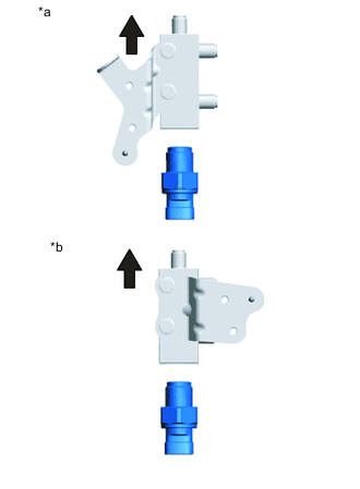
*a for Inlet Side *b for Outlet Side 
Straight Up As shown in the illustration, put the hydrogen tank tube joint in the vertical direction, and from the bottom, temporarily tighten the hydrogen tank pressure sensor until the seal surface contacts.
Note
-
To prevent foreign matter from being caught in the seal surface when tightening, follow this procedure when installing.
-
Do not allow dust, metal fragments, etc. to enter the openings of the hydrogen tank tube joint.
-
Be careful not to scratch or damage the seal portions or threaded portions.
-
-
Secure the hydrogen tank tube joint in a vise between aluminum plates.
Note
-
Be careful not to scratch or damage the seal portions or threaded portions.
-
Do not overtighten the vise.
-
If the hydrogen tank tube joint and hydrogen tank pressure sensor have been dropped or subjected to a strong impact, replace the hydrogen tank tube joint and hydrogen tank pressure sensor with a new one.
-
-
Using a 30 mm deep socket wrench, temporarily tighten the hydrogen tank pressure sensor.
- Torque:
- 10 N*m { 102 kgf*cm, 7 ft.*lbf }
Note
-
After a hydrogen tank pressure sensor has been tightened, if that hydrogen tank pressure sensor is then removed, it must be replaced with a new one.
-
If the hydrogen tank tube joint and hydrogen tank pressure sensor have been dropped or subjected to a strong impact, replace the hydrogen tank tube joint and hydrogen tank pressure sensor with new ones.
-
Be careful not to damage the connector portion of the hydrogen tank pressure sensor with the 30 mm deep socket wrench.
-
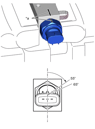
*a Paint Mark Place paint marks on the hydrogen tank pressure sensor and hydrogen tank tube joint.
Tech Tips
Apply the paint marks so they make one straight line.
-
Set a torque wrench to 150 N*m (1530 kgf*cm, 111 ft.*lbf), and using a 30 mm deep socket wrench, use the paint marks as a reference and slowly tighten the hydrogen tank pressure sensor by 55° to 65°.
Note
-
Be careful not to damage the connector portion of the hydrogen tank pressure sensor with the 30 mm deep socket wrench.
-
If the tightening torque reaches 150 N*m (1530 kgf*cm, 111 ft.*lbf) before the tightening angle becomes 55° to 65°, replace the hydrogen tank pressure sensor with a new one.
-
If the tightening torque reaches 150 N*m (1530 kgf*cm, 111 ft.*lbf) before the tightening angle becomes 55° to 65° even after replacing the hydrogen tank pressure sensor with a new one, replace the hydrogen tank pressure sensor and hydrogen tank tube joint with new ones.
Tech Tips
Tightening speed: 30° / second or less
-
-
Set the torque wrench to 80 N*m (816 kgf*cm, 59 ft.*lbf), and check the tightening torque of the hydrogen tank pressure sensor.
Note
-
Be careful not to damage the connector portion of the hydrogen tank pressure sensor with the 30 mm deep socket wrench.
-
If the tightening torque has not reached 80 N*m (816 kgf*cm, 59 ft.*lbf), replace the hydrogen tank pressure sensor with a new one.
-
If the tightening torque has not reached 80 N*m (816 kgf*cm, 59 ft.*lbf) even after replacing the hydrogen tank pressure sensor with a new one, replace the hydrogen tank pressure sensor and hydrogen tank tube joint with new ones.
-
-
-
INSTALL HYDROGEN TANK TUBE JOINT (for Inlet Side)
-
INSTALL HYDROGEN TANK TUBE JOINT (for Outlet Side)