TUBE JOINT(for Outlet Side) INSTALLATION
PROCEDURE
-
INSTALL HYDROGEN TANK PRESSURE SENSOR
Tech Tips
This procedure is only performed when the hydrogen tank tube joint is being replaced with a new one.
-
INSTALL HYDROGEN TANK TUBE JOINT SUPPLY BRACKET
Note
To prevent damage to seal portions or threaded portions, and to prevent openings from being contaminated by dust, metal fragments, etc., do not remove the protective caps of piping connection areas included with new parts until immediately before performing the procedure.
-
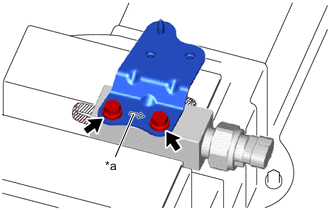
*a Arrow Stamp Secure the hydrogen tank tube joint in a vise between aluminum plates.
Note
-
Be careful not to scratch or damage the seal portions or threaded portions.
-
Do not overtighten the vise.
-
If the hydrogen tank tube joint has been dropped or subjected to a strong impact, replace the hydrogen tank tube joint and hydrogen tank pressure sensor with a new one.
-
-
Install the hydrogen tank tube joint supply bracket to the hydrogen tank tube joint with the 2 bolts.
- Torque:
- 13 N*m { 133 kgf*cm, 10 ft.*lbf }
Note
If the hydrogen tank tube joint has been dropped or subjected to a strong impact, replace the hydrogen tank tube joint and hydrogen tank pressure sensor with a new one.
Tech Tips
Install so that the direction of the arrow stamped on the hydrogen tank tube joint inlet bracket is pointing toward the hydrogen tank pressure sensor side.
-
-
TEMPORARILY TIGHTEN HYDROGEN TANK TUBE JOINT
-
Temporarily tighten the hydrogen tank tube joint to the front center hydrogen tank frame with the 2 bolts.
Note
If the hydrogen tank tube joint has been dropped or subjected to a strong impact, replace the hydrogen tank tube joint and hydrogen tank pressure sensor with a new one.
-
-
TEMPORARILY TIGHTEN NO. 6 HYDROGEN TANK TUBE
-
INSTALL FUEL TUBE GROMMET
-
Engage the claw and install a new fuel tube grommet to the front hydrogen tank frame sub-assembly LH.
-
Engage the clamp and connect the No. 4 hydrogen tank tube to the fuel tube grommet.
Note
-
Do not damage or deform the No. 4 hydrogen tank tube.
-
If the pipe protector material of the No. 4 hydrogen tank tube is damaged so that the internal pipe itself becomes visible, replace the No. 4 hydrogen tank tube with a new one.
-
-
-
TEMPORARILY TIGHTEN NO. 4 HYDROGEN TANK TUBE
-
TEMPORARILY TIGHTEN NO. 5 HYDROGEN TANK TUBE
-
INSTALL FUEL TUBE GROMMET
-
INSTALL NO. 1 FUEL TUBE CLAMP
-
INSTALL HYDROGEN TANK TUBE CLAMP BRACKET
-
FULLY TIGHTEN HYDROGEN TANK TUBE JOINT
-
Fully tighten the 2 installation bolts of the hydrogen tank tube joint.
- Torque:
- 13 N*m { 133 kgf*cm, 10 ft.*lbf }
-
-
FULLY TIGHTEN NO. 6 HYDROGEN TANK TUBE
-
FULLY TIGHTEN NO. 4 HYDROGEN TANK TUBE
-
FULLY TIGHTEN NO. 5 HYDROGEN TANK TUBE
-
INSTALL WIRE HARNESS CLAMP
-
INSTALL HYDROGEN TANK UNIT