FC BOOST CONTROL SYSTEM, Diagnostic DTC:P1D1E-450, P1D1F-450
| DTC Code | DTC Name |
|---|---|
| P1D1E-450 | FC Converter Output Voltage Sensor Circuit Low |
| P1D1F-450 | FC Converter Output Voltage Sensor Circuit High |
DESCRIPTION
The FC converter assembly consists of the 4 phase reactors and power transistor (IGBT). It boosts the voltage output from the FC stack by operating the power transistor based on the output request value which is sent from the EV control ECU, and then outputs the boosted voltage to the inverter with converter assembly.
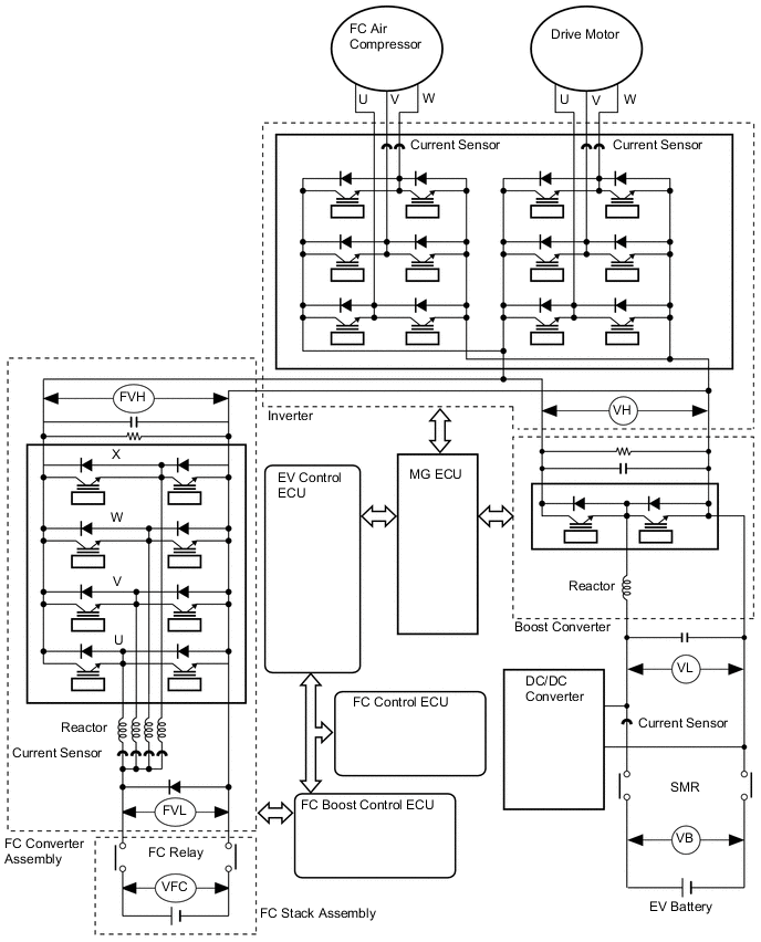
The FC boost control ECU detects high voltage after boosting (FVH) using the FC converter voltage sensor which is located inside the FC converter assembly and controls voltage boosting.
The FC converter voltage sensor changes its output voltage between 0 to 5 V, in accordance with changes in the high voltage (FVH).
The FC boost control ECU monitors the FC converter voltage sensor and detects malfunctions.
| DTC No. | Detection Item | DTC Detection Condition | Trouble Area | Warning Indicate |
|---|---|---|---|---|
| P1D1E-450 | FC Converter Output Voltage Sensor Circuit Low | Voltage sensor (FVH) malfunction FC boost converter output voltage AD value is less than 0.72 V for 0.1 seconds or more continuously (1 trip detection logic) |
FC converter assembly | Master Warning Light: Comes on |
| P1D1F-450 | FC Converter Output Voltage Sensor Circuit High | Voltage sensor (FVH) malfunction FC boost converter output voltage AD value is 4.54 V or more for 0.1 seconds or more continuously (1 trip detection logic) |
FC converter assembly | Master Warning Light: Comes on |
Tech Tips
This is the DTC for failure of the FVH voltage sensor.
| DTC No. | Data List |
|---|---|
| P1D1E-450 |
|
| P1D1F-450 | FC Converter Output Voltage |
CAUTION / NOTICE / HINT
Note
When the vehicle is parked with the power switch off, if the FC control ECU judges that the FC stack temperature will go below 0°C (32°F), it activates the FC air compressor, hydrogen pump and FC cooling water pump for a maximum of 180 seconds and drains water from the FC stack assembly. When performing inspection or repairs with the power switch off (not on (IG) or on (READY)), disconnect the cable from the negative (-) auxiliary battery terminal before performing work (If the auxiliary battery voltage is needed to conduct inspection, warm up the FC system beforehand).
Tech Tips
After the repair, clear the DTCs and perform the following procedure to check that DTCs are not output.
-
Turn the power switch on (READY) and wait for 5 seconds or more.
PROCEDURE
-
REPLACE FC CONVERTER ASSEMBLY
Tech Tips
DTC P1D1E-450 or P1D1F-450 is output, replace the FC converter assembly because the FC converter output voltage (FVH) signal line is connected to the FC boost control ECU inside the FC converter assembly.
Result Proceed to NEXT
NEXT 
END