FC BOOST CONTROL SYSTEM TERMINALS OF ECM
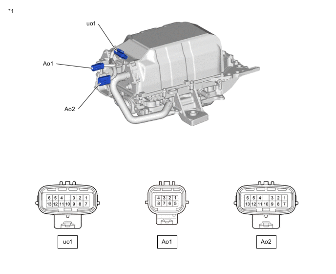
| *1 | FC Converter Assembly Low Voltage Connector | - | - |
| Terminal No. (Symbol) |
Terminal Description | Input/Output | Wiring Color | Condition | Specified Condition |
|---|---|---|---|---|---|
| uo1-6 (FCG+) - uo1-11 (GND) | FC relay (FCG) | Output | B - V | Power switch on (IG) | 0 to 1.5 V |
| Power switch on (READY) | 11 to 15.5 V | ||||
| uo1-1 (FCB+) - uo1-11 (GND) | FC relay (FCB) | Output | W - V | Power switch on (IG) | 0 to 1.5 V |
| Power switch on (READY) | 11 to 15.5 V | ||||
| uo1-5 (ILKI) - uo1-11 (GND) | Interlock switch | Input | R-B - V | Each interlock is correctly assembled | Below 1 V |
| uo1-12 (ILKRI) - uo1-11 (GND) | Interlock switch | Input | P - V | Each interlock is correctly assembled | Below 1 V |
| uo1-4 (CMSP) - uo1-11 (GND) | Cell monitor sleep command | Output | GR - V | Power switch on (READY), Cell monitor in communication | 4.5 to 5.5 V |
| Ao1-1 (ISDN) - Ao1-5 (GND) | Converter fail signal | Input | V - R-L | Power switch on (READY) | Below 1 V |
| Ao1-4 (CMPW) - Ao1-5 (GND) | Cell monitor power source | Input | L-R - R-L | Power switch on (IG) | 11 to 15.5 V |
| Ao1-8 (IG2) - Ao1-5 (GND) | IG2 | Input | G-Y - R-L | Power switch on (IG) | 11 to 15.5 V |
| Ao2-7 (CA1L) - Ao2-5 (E1) | CAN communication signal (V bus) | Input/Output | L - GR | Power switch on (IG) | Pulse generation (Waveform 1) |
| Ao2-1 (CA1H) - Ao2-5 (E1) | CAN communication signal (V bus) | Input/Output | Y - GR | Power switch on (IG) | Pulse generation (Waveform 1) |
| Ao2-8 (CAFL) - Ao2-5 (E1) | CAN communication signal (FC local bus) | Input/Output | BR - GR | Power switch on (IG) | Pulse generation (Waveform 2) |
| Ao2-2 (CAFH) - Ao2-5 (E1) | CAN communication signal (FC local bus) | Input/Output | G-W - GR | Power switch on (IG) | Pulse generation (Waveform 2) |
| Ao2-9 (BATT) - Ao2-5 (E1) | Constant power source | Input | R-W - GR | Always | 11 to 15.5 V |
| Ao2-10 (ILKI) - Ao2-5 (E1) | FC interlock switch | Input | W - GR | Each interlock is correctly assembled | Below 1 V |
| Ao2-4 (FSDN) - Ao2-5 (E1) | Converter shutdown signal | Input | Y-R - GR | Power switch on (READY) | Below 1 V |
| Ao2-6 (+B1) - Ao2-5 (E1) | Power source | Input | W-B - GR | Power switch on (IG) | 11 to 15.5 V |
| Ao2-13 (+B2) - Ao2-5 (E1) | Power source | Input | W-R - GR | Power switch on (IG) | 11 to 15.5 V |
-
Oscilloscope waveforms
Tech Tips
Oscilloscope waveform samples are provided here for informational purposes. Noise and fluttering waveforms have been omitted.
-
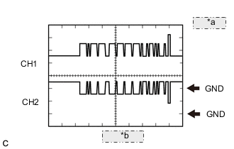
*a 1 V/DIV. *b 50 μs/DIV. Waveform 1 (CAN communication signal)
Item Content Terminal CH1: CA1H - E1
CH2: CA1L - E1
Equipment Setting 1 V/DIV, 50 μs/DIV Condition Power switch on (IG) Tech Tips
The waveform will vary depending on the content of the digital communication (digital signal).
-
*a 1 V/DIV. *b 50 μs/DIV. Waveform 2 (CAN communication signal)
Item Content Terminal CH1: CAFH - E1
CH2: CAFL - E1
Equipment Setting 1 V/DIV, 50 μs/DIV Condition Power switch on (IG) Tech Tips
The waveform will vary depending on the content of the digital communication (digital signal).
-