CONVERTER ASSEMBLY INSTALLATION
PROCEDURE
-
INSTALL FC CONVERTER ASSEMBLY
CAUTION:
Wear insulated gloves.
-
To prevent contamination by foreign matter or water droplets, remove the protective tape from the opening of the FC converter assembly immediately before performing the procedure.
-
Install a new rear FC converter gasket to the FC converter assembly.
Note
-
Do not allow foreign matter to adhere to the surface of the rear FC converter gasket.
-
Perform the procedures by hand. Do not use any tools.
-
Securely press the rear FC converter gasket into the groove of the FC converter assembly to install it.
-
-
To prevent contamination by foreign matter or water droplets, remove the protective tape from the opening of the FC stack assembly immediately before performing the procedure.
-
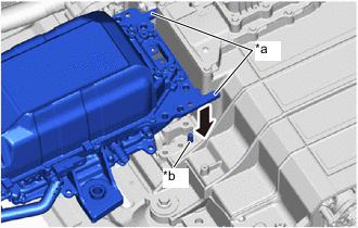
*a Rough Guide *b Assembly Guide Pin 
Lower Vertically Using the rough guide, align the FC converter assembly with the installation position, lower the FC converter assembly vertically and securely engage the assembly guide pin.
Note
-
Do not hold the FC converter assembly by its pipe portion.
-
Be careful not to drop the rear FC converter gasket.
-
Be careful that foreign matter or water droplets do not enter the FC stack assembly and FC converter assembly.
-
If the FC converter assembly has been dropped, damaged or subjected to a strong impact, replace it with a new one.
-
-
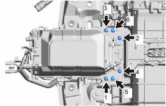
Install the 6 bolts in the order shown in the illustration.
- Torque:
- 62 N*m { 632 kgf*cm, 46 ft.*lbf }
-
Remove the protective tape or similar from the No. 1 FC stack caution label.
-
Install the 2 No. 2 FC stack mounts to the FC converter assembly.
-
Install the 2 bolts.
- Torque:
- 50 N*m { 510 kgf*cm, 37 ft.*lbf }
-
To prevent contamination by foreign matter or water droplets, remove the protective tape from the opening of the FC converter assembly immediately before performing the procedure.
-
Using an insulated tool, install the 2 bolts.
- Torque:
- 8.0 N*m { 82 kgf*cm, 71 in.*lbf }
-
Install a new rear FC converter service hole gasket to the rear FC converter service hole cover.
Note
-
Do not allow foreign matter to adhere to the rear FC converter service hole gasket.
-
Perform the procedures by hand. Do not use any tools.
-
Securely press the rear FC converter service hole gasket into the groove of the rear FC converter service hole cover to install it.
-
-
Install the rear FC converter service hole cover to the FC converter assembly with the 2 bolts.
- Torque:
- 8.0 N*m { 82 kgf*cm, 71 in.*lbf }
Note
-
Be careful that foreign matter or water droplets do not enter the FC converter assembly.
-
Be careful not to drop the rear FC converter service hole gasket.
-
-
INSTALL FC STACK COOLING WATER INLET HOSE
-
To prevent contamination by foreign matter, remove the plastic bags from the connecting portions of the FC stack cooling water inlet hose and FC stack assembly immediately before performing the procedure.
-
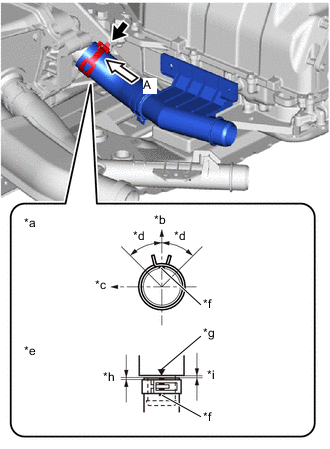
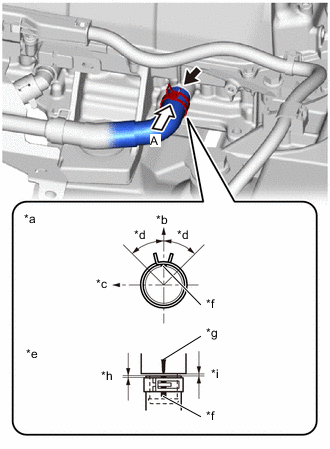
*a View A *b Upper Side of Vehicle *c RH Side of Vehicle *d Area of claw of hose clip: 45° *e Locations of hose tip and hose clip *f Paint Mark (Yellow) *g Matchmark *h Distance between hose tip and hose clip location: 2.0 to 5.0 mm (0.0787 to 0.197 in.) *i Distance between hose tip and FC stack assembly location: 0 to 2.0 mm (0 to 0.0787 in.) Install the FC stack cooling water inlet hose to the FC stack assembly and slide the hose clip to secure it.
Note
Perform the installation with the hose and hose clip at the correct angle.
Tech Tips
When connecting, if it is difficult to insert the FC stack cooling water inlet hose, coat it with new coolant (Toyota genuine FC stack coolant)
-
-
CONNECT FC STACK COOLING WATER INLET PIPE
-
Connect the FC stack cooling water inlet pipe to the FC converter assembly with the 2 bolts.
- Torque:
- 8.0 N*m { 82 kgf*cm, 71 in.*lbf }
-
-
INSTALL WIRE HARNESS CLAMP BRACKET
-
Temporarily install the wire harness clamp bracket to the FC converter assembly with the 2 bolts.
-
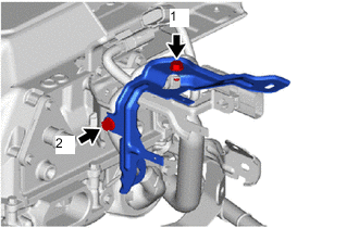
Tighten the 2 bolts in the order shown in the illustration.
- Torque:
- 8.0 N*m { 82 kgf*cm, 71 in.*lbf }
-
-
INSTALL WIRE HARNESS CLAMP BRACKET
-
Engage the 3 clamps to install the 3 wire harness clamp brackets to the wire harness.
-
-
CONNECT WIRE HARNESS
CAUTION:
Wear insulated gloves.
-
Engage the 2 clamps to connect the wire harness to the wire harness clamp bracket.
-
To prevent contamination by foreign matter, remove the plastic bags from the connecting portions of the FC converter cooling water inlet hose and FC converter assembly immediately before performing the procedure.
-
*a View A *b Upper Side of Vehicle *c Front Side of Vehicle *d Area of claw of hose clip: 45° *e Locations of hose tip and hose clip *f Paint Mark (Yellow) *g Matchmark *h Distance between hose tip and hose clip location: 2.0 to 5.0 mm (0.0787 to 0.197 in.) *i Distance between hose tip and FC converter assembly location: 0 to 2.0 mm (0 to 0.0787 in.) Connect the FC converter cooling water inlet hose to the FC converter assembly and slide the hose clip to secure it.
Note
Perform the installation with the hose and hose clip at the correct angle.
-
Install the wire harness clamp bracket to the FC converter assembly with the bolt.
- Torque:
- 8.0 N*m { 82 kgf*cm, 71 in.*lbf }
-
Connect the FC converter cooling water inlet pipe, together with the wire harness, to the FC converter assembly with the 2 bolts.
- Torque:
- 8.0 N*m { 82 kgf*cm, 71 in.*lbf }
-
Connect the connector.
-
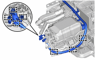
Engage the 7 clamps to connect the wire harness to the wire harness clamp bracket.
-
Install the 3 wire harness clamp brackets to the FC converter assembly and FC stack assembly with the 3 bolts.
- Torque:
- 8.0 N*m { 82 kgf*cm, 71 in.*lbf }
-
Engage the 7 clamps to connect the wire harness and connector to the FC converter assembly and FC stack assembly.
-
-
INSTALL REAR FRAME ASSEMBLY