FC CONTROL SYSTEM Fuel Lid Interlock Circuit
DESCRIPTION
The hydrogen fuel control ECU monitors the fuel lid condition (open/close) by means of the 2 interlock switches that are built into the fuel filler opening lid hinge and the fuel filler opening lid switch sub-assembly. If the 2 interlock switch signals indicate that the fuel lid is open, the hydrogen fuel control ECU prohibits the power switch from being turned on (READY) during hydrogen filling.
If it is found that the fuel lid is open with the power switch off, or signals from the 2 interlock switches are inconsistent with each other, the hydrogen fuel control ECU prohibits the power switch from being turned on (READY) and also the shift lever from being moved from P to other positions.
If the vehicle is in the READY ON mode, even when inconsistency is detected between the 2 interlock switch signals or the open fuel lid is detected, the hydrogen fuel control ECU allows the vehicle to remain in the READY ON mode. However, if the hydrogen tank internal pressure increases due to hydrogen filling when the vehicle is in the READY ON mode, the hydrogen fuel control ECU forcibly cancels the READY ON mode.
Despite the fact that the fuel lid is actually closed, if the multi-information display shows "Close H2 Filler Door and Restart Your Vehicle" or "H2 Filler Door is open. Park Your Vehicle in a Safe Place and Close H2 Filler Door", perform this diagnostic troubleshooting procedure.
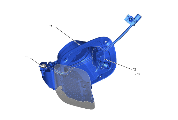
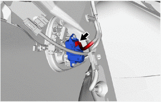
| *1 | Fuel Filler Opening Lid Sub-assembly (Hinge Switch) | *2 | Fuel Filler Opening Lid Switch Sub-assembly |
| *3 | Interlock Switch | - | - |
CAUTION / NOTICE / HINT
Note
When the vehicle is parked with the power switch off, if the FC control ECU judges that the FC stack temperature will go below 0°C (32°F), it activates the FC air compressor, hydrogen pump and FC cooling water pump for a maximum of 180 seconds and drains water from the FC stack assembly. When performing inspection or repairs with the power switch off (not on (IG) or on (READY)), disconnect the cable from the negative (-) auxiliary battery terminal before performing work (If the auxiliary battery voltage is needed to conduct inspection, warm up the FC system beforehand).
Tech Tips
Related Data List
-
Fuel Lid Interlock Switch
| Tester Display | Fuel lid fully closed | Fuel lid fully open |
|---|---|---|
| Fuel Lid Interlock Switch | OFF | ON |
-
Fuel filler opening lid sub-assembly (hinge switch) is stuck closed or open.
-
Fuel filler opening lid sub-assembly (hinge switch) circuit has an open, or is shorted to the GND circuit.
-
Fuel filler opening lid switch sub-assembly is stuck closed or open.
-
Fuel filler opening lid switch sub-assembly circuit has an open, or is shorted to the GND circuit.
Suspected malfunctions
PROCEDURE
-
INSPECT FUEL FILLER OPENING LID SUB-ASSEMBLY (HINGE SWITCH)
Result Proceed to OK NG
NG 
REPLACE FUEL FILLER OPENING LID SUB-ASSEMBLY (HINGE SWITCH) Click here
OK 
-
CHECK HARNESS AND CONNECTOR (HYDROGEN FUEL CONTROL ECU ASSEMBLY - FUEL FILLER OPENING LID SUB-ASSEMBLY (HINGE SWITCH))
-
Disconnect the hydrogen fuel control ECU assembly connector.
-
Disconnect the fuel filler opening lid sub-assembly (hinge switch) connector.
-
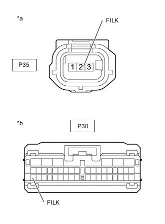
*a Front view of wire harness connector
(to Fuel Filler Opening Lid Sub-assembly (Hinge Switch))
*b Front view of wire harness connector
(to Hydrogen Fuel Control ECU Assembly)
Measure the resistance according to the value(s) in the table below.
Standard Resistance Tester Connection Condition Specified Condition P35-2 (FILK) - P30-23 (FILK) Always Below 1 Ω P35-2 (FILK) or P30-23 (FILK) - Body ground and other terminals Always 10 kΩ or higher -
Reconnect the fuel filler opening lid sub-assembly (hinge switch) connector.
-
Reconnect the hydrogen fuel control ECU assembly connector.
Result Proceed to OK NG
NG
REPAIR OR REPLACE HARNESS OR CONNECTOR
OK
-
-
CHECK HARNESS AND CONNECTOR (FUEL FILLER OPENING LID SUB-ASSEMBLY (HINGE SWITCH) - BODY GROUND)
-
Disconnect the fuel filler opening lid sub-assembly (hinge switch) connector.
-
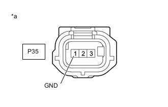
*a Front view of wire harness connector
(to Fuel Filler Opening Lid Sub-assembly (Hinge Switch))
Measure the resistance according to the value(s) in the table below.
Standard Resistance Tester Connection Condition Specified Condition P35-1 (GND) - Body ground Always Below 1 Ω -
Reconnect the fuel filler opening lid sub-assembly (hinge switch) connector.
Result Proceed to OK NG
NG
REPAIR OR REPLACE HARNESS OR CONNECTOR
OK
-
-
INSPECT FUEL FILLER OPENING LID SWITCH SUB-ASSEMBLY
Result Proceed to OK NG
NG
REPLACE FUEL FILLER OPENING LID SWITCH SUB-ASSEMBLY Click here
OK
-
CHECK HARNESS AND CONNECTOR (HYDROGEN FUEL CONTROL ECU ASSEMBLY - FUEL FILLER OPENING LID SWITCH SUB-ASSEMBLY)
-
Disconnect the hydrogen fuel control ECU assembly connector.
-
Disconnect the fuel filler opening lid switch sub-assembly connector.
-
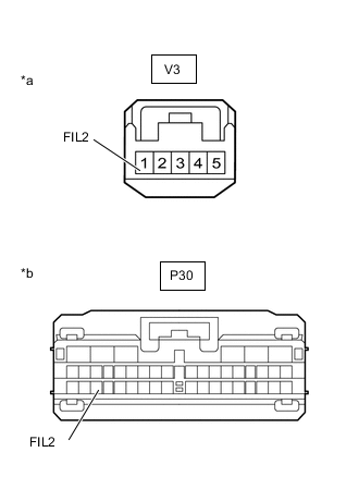
*a Front view of wire harness connector
(to Fuel Filler Opening Lid Switch Sub-assembly)
*b Front view of wire harness connector
(to Hydrogen Fuel Control ECU Assembly)
Measure the resistance according to the value(s) in the table below.
Standard Resistance Tester Connection Condition Specified Condition V3-1 (FIL2) - P30-25 (FIL2) Always Below 1 Ω V3-1 (FIL2) or P30-25 (FIL2) - Body ground and other terminals Always 10 kΩ or higher -
Reconnect the fuel filler opening lid switch sub-assembly connector.
-
Reconnect the hydrogen fuel control ECU assembly connector.
Result Proceed to OK NG
NG
REPAIR OR REPLACE HARNESS OR CONNECTOR
OK
-
-
CHECK HARNESS AND CONNECTOR (FUEL FILLER OPENING LID SWITCH SUB-ASSEMBLY - BODY GROUND)
-
Disconnect the fuel filler opening lid switch sub-assembly connector.
-
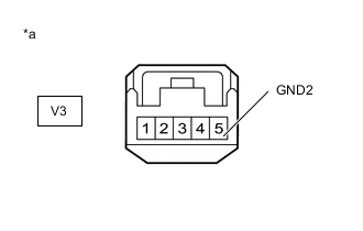
*a Front view of wire harness connector
(to Fuel Filler Opening Lid Switch Sub-assembly)
Measure the resistance according to the value(s) in the table below.
Standard Resistance Tester Connection Condition Specified Condition V3-5 (GND2) - Body ground Always Below 1 Ω -
Reconnect the fuel filler opening lid switch sub-assembly connector.
Result Proceed to OK NG
OK
PROCEED TO NEXT SUSPECTED AREA SHOWN IN PROBLEM SYMPTOMS TABLE Click here
NG
REPAIR OR REPLACE HARNESS OR CONNECTOR
-