FC CONTROL SYSTEM FC Water Release Switch Circuit
DESCRIPTION
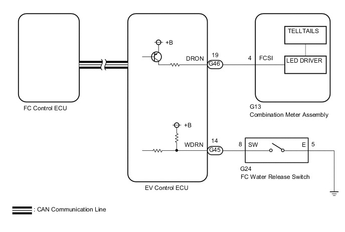
When the FC water release switch is pressed, a drainage request signal will be transmitted to the EV control ECU and FC control ECU, and if conditions have been satisfied, produced water will be drained. At this time, a drainage process signal is transmitted from the FC control ECU to the combination meter, the H2O indicator light will be illuminated.
This troubleshooting procedure is for a symptom that the H2O indicator light remains off even when the FC water release switch is pressed although the power switch has been turned on (IG or READY).
WIRING DIAGRAM
CAUTION / NOTICE / HINT
Note
When the vehicle is parked with the power switch off, if the FC control ECU judges that the FC stack temperature will go below 0°C (32°F), it activates the FC air compressor, hydrogen pump and FC cooling water pump for a maximum of 180 seconds and drains water from the FC stack assembly. When performing inspection or repairs with the power switch off (not on (IG) or on (READY)), disconnect the cable from the negative (-) auxiliary battery terminal before performing work (If the auxiliary battery voltage is needed to conduct inspection, warm up the FC system beforehand).
Tech Tips
| - | FC water release switch | H2O indicator light | Tester Display (EV) | |
|---|---|---|---|---|
| H2O Indicator | H2O Switch | |||
| Power switch off | ON | Does not come on | - | - |
| Power switch on (IG) | ON | Comes on * | ON | ON |
| Power switch on (READY) | ON | Comes on | ON | ON |
-
*: H2O indicator light does come on for 1 second just after the power switch on (IG).
Produced water is allowed to come out from the FC exhaust tail pipe when the FC water release switch is pressed with the following conditions met.
-
Power switch on (READY)
-
The Data List that "FC Mode" is FC Working*
-
FC stack drainage conditions are met
-
*: When the FC water release switch is pressed with the "FC Mode" of the Data List in the FC Startup Process, drainage will begin after the "FC Mode" enters the FC Working.
PROCEDURE
-
CHECK DTC OUTPUT (HEALTH CHECK)
-
Connect the GTS to the DLC3.
-
Turn the power switch on (IG).
-
Turn the GTS on.
-
Enter the following menus: System Select / Health Check.
-
Check for DTCs.
Result Result Proceed to DTCs are not output A DTCs are output. B -
Turn the power switch off.
B 
GO TO DTC CHART
A 
-
-
READ VALUE USING GTS (H2O INDICATOR, H2O SWITCH)
-
Connect the GTS to the DLC3.
-
Turn the power switch on (READY).
-
Enter the following menus: Powertrain / EV / Data List / H2O Indicator, H2O Switch
Powertrain > EV > Data ListTester Display Measurement Item Range Normal Condition Diagnostic Note H2O Indicator State of the H2O indicator light in the combination meter ON or OFF Power switch on (READY):
OFF
H2O indicator light illuminated:
ON
- H2O Switch FC water release switch condition ON or OFF FC water release switch being pushed and held:
ON
-
Powertrain > EV > Data ListTester Display H2O Indicator H2O Switch -
Press the FC water release switch.
-
Read the value displayed on the GTS.
Result Result Proceed to Data List display does change in accordance with the switch operation A Data List display does not change in accordance with the switch operation B -
Turn the power switch off.
B 
CHECK EV CONTROL ECU (FC WATER RELEASE SWITCH SIGNAL) Click here
A
-
-
CHECK EV CONTROL ECU (H2O INDICATOR)
-
Connect the GTS to the DLC3.
-
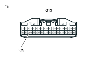
*a Front view of wire harness connector
(to Combination Meter Assembly)
Disconnect the combination meter assembly connector.
-
Turn the power switch on (READY) with the shift lever in P, and check the Data List that "FC Mode" is FC Working.
-
Turn the GTS on.
-
Enter the following menus: Powertrain / EV / Data List / H2O Indicator
Powertrain > EV > Data ListTester Display H2O Indicator -
Press the FC water release switch to turn on the "H2O Indicator" in the Data List.
-
Measure the voltage according to the value(s) in the table below.
Standard Voltage Tester Connection Condition Specified Condition G13-4 (FCSI) - Body ground "H2O Indicator" of the data list shows ON 11 to 15.5 V -
Turn the power switch off.
-
Reconnect the combination meter assembly connector.
Result Proceed to OK NG
OK
GO TO METER / GAUGE SYSTEM Click here
NG
-
-
CHECK HARNESS AND CONNECTOR (EV CONTROL ECU - COMBINATION METER ASSEMBLY)
-
Disconnect the EV control ECU connector.
-
Disconnect the combination meter assembly connector.
-
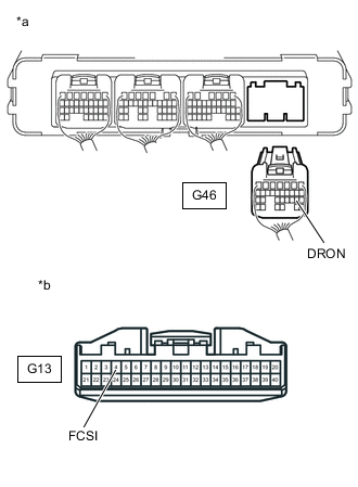
*a Rear view of wire harness connector
(to EV Control ECU)
*b Front view of wire harness connector
(to Combination Meter Assembly)
Measure the resistance according to the value(s) in the table below.
Standard Resistance Tester Connection Condition Specified Condition G46-19 (DRON) - G13-4 (FCSI) Always Below 1 Ω G46-19 (DRON) or G13-4 (FCSI) - Body ground Always 10 kΩ or higher -
Reconnect the combination meter assembly connector.
-
Reconnect the EV control ECU connector.
Result Proceed to OK NG
OK
REPLACE EV CONTROL ECU Click here
NG
REPAIR OR REPLACE HARNESS OR CONNECTOR
-
-
CHECK EV CONTROL ECU (FC WATER RELEASE SWITCH SIGNAL)
-
Disconnect the FC water release switch connector.
-
Turn the power switch on (IG).
-
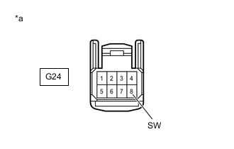
*a Front view of wire harness connector
(to FC Water Release Switch)
Measure the voltage according to the value(s) in the table below.
Standard Voltage Tester Connection Condition Specified Condition G24-8 (SW) - Body ground Power switch on (IG) 11 to 14 V -
Turn the power switch off.
-
Reconnect the FC water release switch connector.
Result Proceed to OK NG
NG
CHECK HARNESS AND CONNECTOR (EV CONTROL ECU - FC WATER RELEASE SWITCH) Click here
OK
-
-
INSPECT FC WATER RELEASE SWITCH
Result Proceed to OK NG
NG
REPLACE FC WATER RELEASE SWITCH Click here
OK
-
CHECK HARNESS AND CONNECTOR (FC WATER RELEASE SWITCH - BODY GROUND)
-
Disconnect the FC water release switch connector.
-
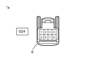
*a Front view of wire harness connector
(to FC Water Release Switch)
Measure the resistance according to the value(s) in the table below.
Standard Resistance Tester Connection Condition Specified Condition G24-5 (E) - Body ground Always Below 1 Ω -
Reconnect the FC water release switch connector.
Result Proceed to OK NG
OK
CHECK FOR INTERMITTENT PROBLEMS Click here
NG
REPAIR OR REPLACE HARNESS OR CONNECTOR
-
-
CHECK HARNESS AND CONNECTOR (EV CONTROL ECU - FC WATER RELEASE SWITCH)
-
Disconnect the EV control ECU connector.
-
Disconnect the FC water release switch connector.
-
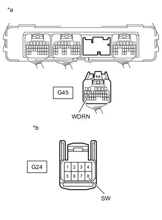
*a Rear view of wire harness connector
(to EV Control ECU)
*b Front view of wire harness connector
(to FC Water Release Switch)
Measure the resistance according to the value(s) in the table below.
Standard Resistance Tester Connection Condition Specified Condition G45-14 (WDRN) - G24-8 (SW) Always Below 1 Ω G45-14 (WDRN) or G24-8 (SW) - Body ground Always 10 kΩ or higher -
Reconnect the FC water release switch connector.
-
Reconnect the EV control ECU connector.
Result Proceed to OK NG
OK
REPLACE EV CONTROL ECU Click here
NG
REPAIR OR REPLACE HARNESS OR CONNECTOR
-