FC CONTROL SYSTEM, Diagnostic DTC:P1E49-450
| DTC Code | DTC Name |
|---|---|
| P1E49-450 | Mass Air Flow Temperature Sensor Correlation |
DESCRIPTION
The air system feeds the FC stack with a necessary amount of oxygen for power generation. The mass air flow meter, which is a part of the air system, has a built-in intake air temperature sensor that measures an ambient temperature for the FC stack. An intake air volume measured by the mass air flow meter is corrected in accordance with changes in an air temperature that is monitored by the intake air temperature sensor.
When an intake air temperature sensor value is compared to another sensor value that is supposed to be equal to the said sensor value, if it has deviated from other values by more than a threshold, it will be interpreted as occurrence of abnormal sensor deviation, and this DTC will be set.
For the circuit diagram, refer to DTC P0101-450.
| DTC No. | Detection Item | DTC Detection Condition | Trouble Area | Warning Indicate |
|---|---|---|---|---|
| P1E49-450 | Mass Air Flow Temperature Sensor Correlation | While the vehicle is traveling and the air compressor is operating, the intake air temperature sensor value of the mass air flow meter has significantly deviated from the ambient temperature value of the air conditioning amplifier. (3 times) |
Mass air flow meter | Master Warning Light: Comes on |
| Vehicle Condition | FC shutdown (power switch on (IG)) |
FC startup process | FC intermittent operation | FC is generating power (vehicle is in stationary) |
FC is generating power (vehicle is traveling) |
FC shutdown process |
|---|---|---|---|---|---|---|
| Data List "FC Mode" |
FC Shutdown | FC Startup Process | FC Working | FC Shutdown Process | ||
| Data List "FC Intermittent Operation" |
OFF | ON | OFF | OFF | ||
| DTC Detection | - | - | - | - | ○ | - |
| DTC No. | System | Data List |
|---|---|---|
| P1E49-450 | FC | Smoothed Value of Intake Air Temperature |
| Air Conditioner | Ambient Temp Sensor |
Tech Tips
This DTC will be output even if ambient temperature sensor values of the air conditioning amplifier are abnormal.
The following items can be helpful when performing repairs:
-
Vehicle Speed
-
Shift Sensor Shift Position
-
Accelerator Degree
-
Ready
-
FC Mode
-
FC Intermittent Operation
-
FC Voltage before Boosting
-
FC Current
-
Target Low-range Hydrogen Pressure
-
Smoothed Value of Low-range Hydrogen Pressure
-
Target Hydrogen Pump Revolution
-
Hydrogen Pump Revolution
-
Target FC Stack Air Pressure (FC Stack Inlet)
-
Smoothed Value of FC Stack Air Pressure (FC Stack Inlet)
-
Target Mass Air Flow Value
-
Mass Air Flow Value
-
Target Air Compressor Revolution
-
Air Compressor Revolution
-
Target FC Stack Coolant Temperature (FC Stack Outlet)
-
Smoothed Value of FC Stack Coolant Temperature (FC Stack Outlet)
-
Exhaust Drainage Valve Driving Request
Common Data List items for FC inspection
CAUTION / NOTICE / HINT
Note
When the vehicle is parked with the power switch off, if the FC control ECU judges that the FC stack temperature will go below 0°C (32°F), it activates the FC air compressor, hydrogen pump and FC cooling water pump for a maximum of 180 seconds and drains water from the FC stack assembly. When performing inspection or repairs with the power switch off (not on (IG) or on (READY)), disconnect the cable from the negative (-) auxiliary battery terminal before performing work (If the auxiliary battery voltage is needed to conduct inspection, warm up the FC system beforehand).
Tech Tips
After the repair, clear the DTCs and perform the following procedure to check that DTCs are not output.
-
Drive the vehicle at a speed of approximately 40 to 60 km/h (25 to 37 mph) for at least 5 minutes (Vehicle does not have to run continuously at the speeds).
CAUTION:
Perform this road test only in an appropriate safe location, in accordance with all local laws.
PROCEDURE
-
CHECK DTC OUTPUT
Note
The freeze frame data is cleared when DTCs are cleared. Be sure to make a note of necessary data in advance.
-
Connect the GTS to the DLC3.
-
Turn the power switch on (IG).
-
Turn the GTS on.
-
Enter the following menus: Powertrain / FC / Trouble Codes.
-
Check for DTCs.
Powertrain > FC > Trouble Codes -
Turn the power switch off.
Result Proceed to NEXT
NEXT 
-
-
CLEAR DTC
-
Connect the GTS to the DLC3.
-
Turn the power switch on (IG).
-
Turn the GTS on.
-
Enter the following menus: Powertrain / FC / Trouble Codes.
-
Clear the DTCs.
Powertrain > FC > Clear DTCs -
Turn the power switch off and wait for 3 minutes or more.
Result Proceed to NEXT
NEXT
-
-
READ VALUE USING GTS (SMOOTHED VALUE OF INTAKE AIR TEMPERATURE)
-
Connect the GTS to the DLC3.
-
Turn the power switch on (IG).
-
Turn the GTS on.
-
Enter the following menus: Powertrain / FC / Data List / Smoothed Value of Intake Air Temperature
Powertrain > FC > Data ListTester Display Smoothed Value of Intake Air Temperature -
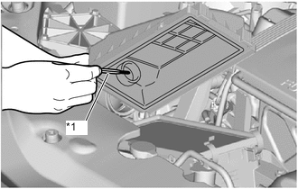
*1 Thermometer Remove the air cleaner cap sub-assembly, and measure the temperature around the mass air flow meter inside the air cleaner case sub-assembly.
-
Compare the temperature around the mass air flow meter and the "Smoothed Value of Intake Air Temperature" in the Data List.
Result Result Proceed to Except the following. A Difference between the "Smoothed Value of Intake Air Temperature" and the temperature around the mass air flow meter is more than 10°C (50°F). B -
Turn the power switch off.
B 
REPLACE MASS AIR FLOW METER Click here
A
-
-
READ VALUE USING GTS (AMBIENT TEMP SENSOR)
-
Connect the GTS to the DLC3.
-
Turn the power switch on (IG).
-
Turn the GTS on.
-
Enter the following menus: Body Electrical / Air Conditioner / Data List / Ambient Temp Sensor
Body Electrical > Air Conditioner > Data ListTester Display Ambient Temp Sensor -
Measure the temperature around the ambient temperature sensor.
-
Compare the temperature around the ambient temperature sensor and the Data List item "Ambient Temp Sensor".
Note
Ambient temperature sensor output is influenced by sunlight, so if the vehicle had been parked outdoor for a long time, a sensor value will increase.
Result Result Proceed to Except the following. A Difference between Data List item "Ambient Temp Sensor" and temperature of area around ambient temperature sensor is 10°C (50°F) or more. B -
Turn the power switch off.
A
CHECK FOR INTERMITTENT PROBLEMS Click here
B
GO TO AIR CONDITIONING SYSTEM Click here
-