FC CONTROL SYSTEM, Diagnostic DTC:P1E42-450
| DTC Code | DTC Name |
|---|---|
| P1E42-450 | Hydrogen Pressure Leak (Excessive Hydrogen Flow) |
DESCRIPTION
The hydrogen system of the FC system feeds the FC stack with hydrogen, so that the FC stack can generate power.
The hydrogen supply line, which is from the tank shut valves up to the hydrogen injectors, are maintained at a higher hydrogen pressure than the pressure applied to the FC stack, and it consists of the high-range pressure area where the pressure equal to the hydrogen tank pressure is applied, and the medium-range pressure area.
Pressures in the hydrogen supply line located between the tank shut valves and hydrogen injectors are monitored by the system, and if the monitored pressure has decreased excessively, this will be interpreted as occurrence of a large amount of hydrogen leakage due to damage in the line, and the DTC will be set.
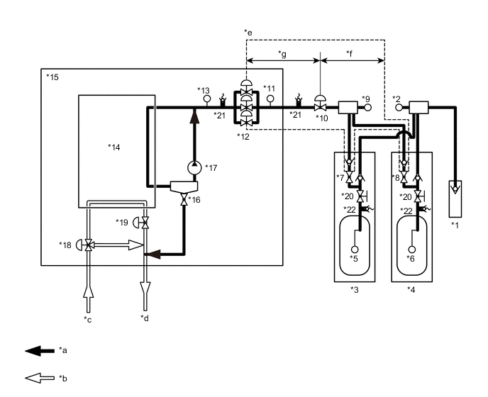
| *1 | Hydrogen Inlet Receptacle Assembly | *2 | Hydrogen Tank Pressure Sensor (for Inlet Side) |
| *3 | No. 1 Hydrogen Tank Assembly | *4 | No. 2 Hydrogen Tank Assembly |
| *5 | Hydrogen Tank Temperature Sensor 1 | *6 | Hydrogen Tank Temperature Sensor 2 |
| *7 | Tank Shut Valve 1 | *8 | Tank Shut Valve 2 |
| *9 | Hydrogen Tank Pressure Sensor (for Outlet Side) | *10 | Hydrogen Supply Regulator Assembly |
| *11 | Medium-range Hydrogen Pressure Sensor | *12 | Hydrogen Injector |
| *13 | Low-range Hydrogen Pressure Sensor | *14 | FC Stack |
| *15 | FC Stack Assembly | *16 | Exhaust Drainage Valve |
| *17 | Hydrogen Pump | *18 | Air Shunt Valve |
| *19 | Air Pressure Regulating Valve | *20 | Manual Valve |
| *21 | Pressure Relief Valve | *22 | Pressure Relief Device |
| *a | Hydrogen System | *b | Air System |
| *c | From the FC Air Compressor with Motor Assembly | *d | To the Exhaust Drainage Pipe |
| *e | Hydrogen Supply Line | *f | High-range Pressure Area |
| *g | Medium-range Pressure Area | - | - |
| DTC No. | Detection Item | DTC Detection Condition | Trouble Area | Warning Indicate |
|---|---|---|---|---|
| P1E42-450 | Hydrogen Pressure Leak (Excessive Hydrogen Flow) | Pressure is monitored all the time while the FC is operating, and the DTC will be set if the high-range or medium-range hydrogen pressure has decreased abruptly. (1 trip detection logic) |
|
Master Warning Light: Comes on |
Tech Tips
-
This DTC indicates leaks in the high- and medium-range hydrogen pressure system, which covers from the hydrogen tanks to hydrogen injectors.
-
Troubleshoot hydrogen leaks from the high-range pressure area first.
| Vehicle Condition | FC shutdown (power switch on (IG)) |
FC startup process | FC intermittent operation | FC is generating power (vehicle is in stationary) |
FC is generating power (vehicle is traveling) |
FC shutdown process |
|---|---|---|---|---|---|---|
| Data List "FC Mode" |
FC Shutdown | FC Startup Process | FC Working | FC Shutdown Process | ||
| Data List "FC Intermittent Operation" |
OFF | ON | OFF | OFF | ||
| DTC Detection | - | - | ○ | ○ | ○ | - |
Tech Tips
By accessing the "FC Mode" and "FC Intermittent Operation" in the freeze frame data, the FC system condition at the time the malfunction occurred can be checked.
| DTC No. | Data List |
|---|---|
| P1E42-450 |
|
Tech Tips
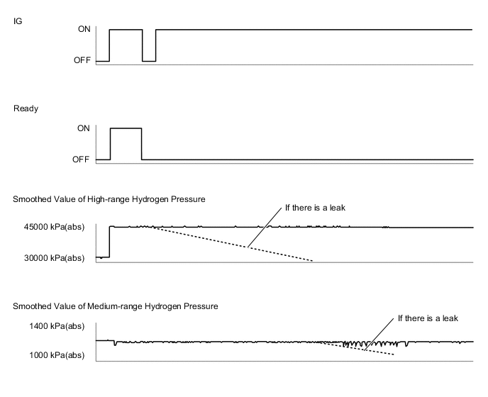
By performing the instructions below, leaks from the high- or medium-range hydrogen pressure system can be identified to some extent by the changes in the "Smoothed Value of High-range Hydrogen Pressure" and "Smoothed Value of Medium-range Hydrogen Pressure" with the power switch on (IG).
-
Turn the power switch on (READY) with the shift lever in P.
-
Turn the power switch off.
-
Turn the power switch on (IG), and observe changes in the "Smoothed Values of High-range Hydrogen Pressure" and "Smoothed Values of Medium-range Hydrogen Pressure" in the Data List.
Figure 1. Reference example
-
When the power switch is on (IG), as the tank shut valves and hydrogen injectors are closed, the high- and medium-range hydrogen pressures do not show significant variations in their values, and they are stable.
-
If hydrogen leakage is suspected, the FC system forces all tank shut valves and hydrogen injectors to close and a decrease in the pressure will be checked during the FC Startup Process.
The following items can be helpful when performing repairs:
-
Tank Shut Valve 1 Driving Request
-
Tank Shut Valve 2 Driving Request
-
Hydrogen Injector 1 Injection Request
-
Hydrogen Injector 2 Injection Request
-
Hydrogen Injector 3 Injection Request
-
Motor Room Side Hydrogen Detector Density
-
Tank Side Hydrogen Detector Density
Data List
-
Vehicle Speed
-
Shift Sensor Shift Position
-
Accelerator Degree
-
Ready
-
FC Mode
-
FC Intermittent Operation
-
FC Voltage before Boosting
-
FC Current
-
Smoothed Value of Low-range Hydrogen Pressure
-
Target Hydrogen Pump Revolution
-
Hydrogen Pump Revolution
-
Target FC Stack Air Pressure (FC Stack Inlet)
-
Smoothed Value of FC Stack Air Pressure (FC Stack Inlet)
-
Target Mass Air Flow Value
-
Mass Air Flow Value
-
Target Air Compressor Revolution
-
Air Compressor Revolution
-
Target FC Stack Coolant Temperature (FC Stack Outlet)
-
Smoothed Value of FC Stack Coolant Temperature (FC Stack Outlet)
-
Exhaust Drainage Valve Driving Request
Common Data List items for FC inspection
CAUTION / NOTICE / HINT
CAUTION:
-
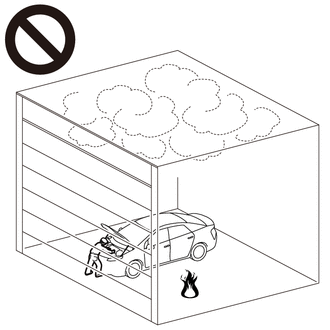
Work procedures must be performed in an area with good ventilation (airflow) where hydrogen gas will not accumulate, and flames or other things that could act as ignition sources must not be present.
-
Accumulated hydrogen gas could ignite, resulting in a serious accident.
-
This DTC indicates a large amount of hydrogen leakage, so perform operations in a well-ventilated area and listen carefully for the sound of leaking hydrogen gas. Use a hydrogen gas detector, and be extremely cautions due to possible hydrogen gas leaks.
Note
-
After completion of repair, check that no hydrogen leaks from the hydrogen pipes using a hydrogen gas detector.
-
When the vehicle is parked with the power switch off, if the FC control ECU judges that the FC stack temperature will go below 0°C (32°F), it activates the FC air compressor, hydrogen pump and FC cooling water pump for a maximum of 180 seconds and drains water from the FC stack assembly. When performing inspection or repairs with the power switch off (not on (IG) or on (READY)), disconnect the cable from the negative (-) auxiliary battery terminal before performing work (If the auxiliary battery voltage is needed to conduct inspection, warm up the FC system beforehand).
Tech Tips
After the repair, clear the DTCs and perform the following procedure to check that DTCs are not output.
-
Turn the power switch on (READY) with the shift lever in P, and check the Data List that "FC Mode" is FC Working. Then, wait for 1 minute or more (If FC system cannot be activated, check the DTCs that are present at the time).
-
Turn the Power switch off and wait for 3 minutes or more.
PROCEDURE
-
CHECK DTC OUTPUT
Note
The freeze frame data is cleared when DTCs are cleared. Be sure to make a note of necessary data in advance.
-
Connect the GTS to the DLC3.
-
Turn the power switch on (IG).
-
Turn the GTS on.
-
Enter the following menus: Powertrain / FC / Trouble Codes.
-
Check for DTCs.
Powertrain > FC > Trouble Codes -
Turn the power switch off.
Result Proceed to NEXT
NEXT 
-
-
CLEAR DTC
-
Connect the GTS to the DLC3.
-
Turn the power switch on (IG).
-
Turn the GTS on.
-
Enter the following menus: Powertrain / FC / Trouble Codes.
-
Clear the DTCs.
Powertrain > FC > Clear DTCs -
Turn the power switch off and wait for 3 minutes or more.
Result Proceed to NEXT
NEXT
-
-
CHECK HYDROGEN GAS LEAKAGE POINT
CAUTION:
-
Work procedures must be performed in an area with good ventilation (airflow) where hydrogen gas will not accumulate, and flames or other things that could act as ignition sources must not be present.
-
Accumulated hydrogen gas could ignite, resulting in a serious accident.
-
Open the hood with the power switch off, check for hydrogen leaks around the underbody and in the motor compartment with a hydrogen gas detector. If leakage is found, pay extra attention to fire safety in the following operations.
-
Turn the power switch off.
-
Remove the under cover.
-
Check that the hydrogen tank and hydrogen pipes are not damaged.
-
Check for a gas leaking sound, and then check if there are hydrogen leaks in the hydrogen pipes and components (high- and medium-range pressures area) with a hydrogen gas detector.
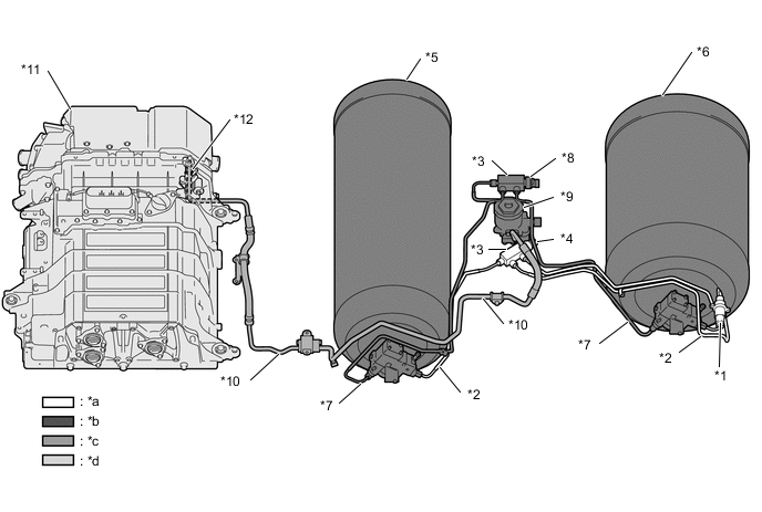
*1 Hydrogen Inlet Receptacle Assembly *2 High-range Hydrogen Pressure Pipe (for filling) *3 Hydrogen Tank Tube Joint *4 Hydrogen Tank Pressure Sensor (for Inlet Side) *5 No. 1 Hydrogen Tank Assembly *6 No. 2 Hydrogen Tank Assembly *7 High-range Hydrogen Pressure Pipe (for feeding) *8 Hydrogen Tank Pressure Sensor (for Outlet Side) *9 Hydrogen Supply Regulator Assembly *10 Medium-range Hydrogen Pressure Pipe *11 FC Stack Assembly *12 Hydrogen Injector *a High-range Pressure Area (when filling)
(Hydrogen Inlet Receptacle Assembly → Hydrogen Tank Assembly )
*b High-range Pressure Area
(Hydrogen Tank Assembly → Hydrogen Supply Regulator Assembly)
*c Medium-range Pressure Area
(Hydrogen Supply Regulator Assembly → Hydrogen Injector)
*d Low-range Pressure Area
(Hydrogen Injector → FC Stack)
Standard value 300 ppm or less. (Hydrogen gas detector) Result Proceed to OK NG
NG 
CHECK HYDROGEN GAS LEAK Click here
OK
-
-
CHECK HYDROGEN GAS LEAKAGE POINT
CAUTION:
-
Work procedures must be performed in an area with good ventilation (airflow) where hydrogen gas will not accumulate, and flames or other things that could act as ignition sources must not be present.
-
Accumulated hydrogen gas could ignite, resulting in a serious accident.
-
Open the hood with the power switch off, check for hydrogen leaks around the underbody and in the motor compartment with a hydrogen gas detector. If leakage is found, pay extra attention to fire safety in the following operations.
Note
Turning the power switch on (READY) causes the tank shut valve to open, and this pressurizes hydrogen in the hydrogen pipes. At this time, locate leaking areas of the hydrogen pipe. If there are leaks, the hydrogen pressure in the pipe decreases gradually, so perform checks quickly.
-
Remove the under cover.
-
Turn the power switch on (READY).
-
Turn the power switch off.
-
Check for a gas leaking sound, and then check if there are hydrogen leaks in the hydrogen pipes and components (high- and medium-range pressures area) with a hydrogen gas detector.
*1 Hydrogen Inlet Receptacle Assembly *2 High-range Hydrogen Pressure Pipe (for filling) *3 Hydrogen Tank Tube Joint *4 Hydrogen Tank Pressure Sensor (for Inlet Side) *5 No. 1 Hydrogen Tank Assembly *6 No. 2 Hydrogen Tank Assembly *7 High-range Hydrogen Pressure Pipe (for feeding) *8 Hydrogen Tank Pressure Sensor (for Outlet Side) *9 Hydrogen Supply Regulator Assembly *10 Medium-range Hydrogen Pressure Pipe *11 FC Stack Assembly *12 Hydrogen Injector *a High-range Pressure Area (when filling)
(Hydrogen Inlet Receptacle Assembly → Hydrogen Tank Assembly )
*b High-range Pressure Area
(Hydrogen Tank Assembly → Hydrogen Supply Regulator Assembly)
*c Medium-range Pressure Area
(Hydrogen Supply Regulator Assembly → Hydrogen Injector)
*d Low-range Pressure Area
(Hydrogen Injector → FC Stack)
Standard value 300 ppm or less. (Hydrogen gas detector) Result Proceed to OK NG -
Install the under cover.
NG
CHECK HYDROGEN GAS LEAK Click here
OK
-
-
CHECK DTC OUTPUT
-
Connect the GTS to the DLC3.
-
Turn the power switch on (IG).
-
Turn the GTS on.
-
Enter the following menus: Powertrain / FC / Trouble Codes.
-
Check for DTCs.
Powertrain > FC > Trouble CodesResult Result Proceed to DTC P1E42-450 is output* A DTCs are not output B
-
*: Inside the FC stack case, upstream of the hydrogen injector, there is medium-range hydrogen pressure piping. If there are no external leaks detected in the hydrogen pipes and components (high-range pressure and medium-range pressure) up to the FC stack assembly but P1E42-450 is detected, it can be determined that there is a hydrogen leak from the medium-range pressure area inside the FC stack case, so replace the FC stack assembly.
-
-
Turn the power switch off.
A 
REPLACE FC STACK ASSEMBLY Click here
B
CHECK FOR INTERMITTENT PROBLEMS Click here
-
-
CHECK HYDROGEN GAS LEAK
CAUTION:
-
Work procedures must be performed in an area with good ventilation (airflow) where hydrogen gas will not accumulate, and flames or other things that could act as ignition sources must not be present.
-
Accumulated hydrogen gas could ignite, resulting in a serious accident.
-
Turn the power switch on (READY).
-
Turn the power switch off.
-
Apply soapy water to locate hydrogen leaking areas.
Result Proceed to NEXT
NEXT
REPLACE MALFUNCTIONING PARTS
-
-
CHECK HYDROGEN GAS LEAK
CAUTION:
-
Work procedures must be performed in an area with good ventilation (airflow) where hydrogen gas will not accumulate, and flames or other things that could act as ignition sources must not be present.
-
Accumulated hydrogen gas could ignite, resulting in a serious accident.
-
Apply soapy water to locate hydrogen leaking areas.
Result Proceed to NEXT
NEXT
REPLACE MALFUNCTIONING PARTS
-