FC CONTROL SYSTEM, Diagnostic DTC:P1E02-450, P1E12-450
| DTC Code | DTC Name |
|---|---|
| P1E02-450 | Tank Shut Valve1 Circuit Low |
| P1E12-450 | Tank Shut Valve2 Circuit Low |
DESCRIPTION
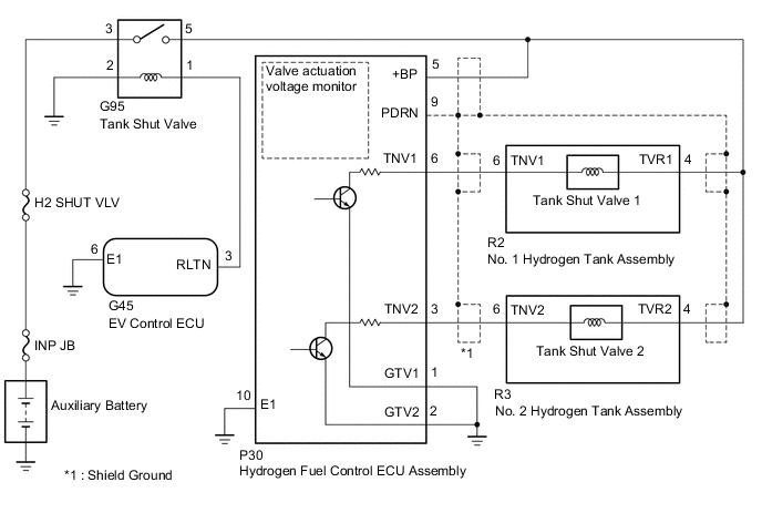
The tank shut valve is built into the hydrogen tank assembly so as to feed or shut off compressed hydrogen from the hydrogen tank to the FC stack. Actuation requests are made by the FC control ECU, and the hydrogen fuel control ECU receives such requests through CAN communication, and then actuates the tank shut valve. The hydrogen fuel control ECU uses the inrush current circuit when opening the valve, and uses the PWM circuit when holding the valve.
The hydrogen fuel control ECU detects abnormalities by monitoring valve actuation voltages.
The EV control ECU operates the tank shut valve relay.
| DTC No. | Detection Item | DTC Detection Condition | Trouble Area | Warning Indicate |
|---|---|---|---|---|
| P1E02-450 | Tank Shut Valve1 Circuit Low | Tank shut valve relay has been requested to turn ON, the tank shut valve 1 is driven to ON, and the TNV1 voltage has remained at less than 0.3 V for more than 3 seconds. (1 trip detection logic) |
|
Master Warning Light: Comes on |
| P1E12-450 | Tank Shut Valve2 Circuit Low | Tank shut valve relay has been requested to turn ON, the tank shut valve 2 is driven to ON, and the TNV2 voltage has remained at less than 0.3 V for more than 3 seconds. (1 trip detection logic) |
|
Master Warning Light: Comes on |
| Vehicle Condition | FC shutdown (power switch on (IG)) |
FC startup process | FC intermittent operation | FC is generating power (vehicle is in stationary) |
FC is generating power (vehicle is traveling) |
FC shutdown process |
|---|---|---|---|---|---|---|
| Data List "FC Mode" |
FC Shutdown | FC Startup Process | FC Working | FC Shutdown Process | ||
| Data List "FC Intermittent Operation" |
OFF | ON | OFF | OFF | ||
| DTC Detection | - | ○ | ○ | ○ | ○ | ○ |
Tech Tips
By accessing the "FC Mode" and "FC Intermittent Operation" in the freeze frame data, the FC system condition at the time the malfunction occurred can be checked.
| DTC No. | Data List |
|---|---|
| P1E02-450 |
|
| P1E12-450 |
|
-
*1: AD value for the TNV1 and 2 terminals
-
*2: Actuation request to the power supply relay
WIRING DIAGRAM
CAUTION / NOTICE / HINT
Note
-
Inspect the fuses of circuits related to this system before performing the following procedure.
-
When the vehicle is parked with the power switch off, if the FC control ECU judges that the FC stack temperature will go below 0°C (32°F), it activates the FC air compressor, hydrogen pump and FC cooling water pump for a maximum of 180 seconds and drains water from the FC stack assembly. When performing inspection or repairs with the power switch off (not on (IG) or on (READY)), disconnect the cable from the negative (-) auxiliary battery terminal before performing work (If the auxiliary battery voltage is needed to conduct inspection, warm up the FC system beforehand).
Tech Tips
After the repair, clear the DTCs and perform the following procedure to check that DTCs are not output.
-
Turn the power switch on (READY) with the shift lever in P and wait for 1 minute or more.
PROCEDURE
-
CHECK DTC OUTPUT
-
Connect the GTS to the DLC3.
-
Turn the power switch on (IG).
-
Turn the GTS on.
-
Enter the following menus: Powertrain / FC / Trouble Codes.
-
Check for DTCs.
Powertrain > FC > Trouble CodesResult Result Proceed to DTC P1E02-450 is output A DTC P1E12-450 is output B DTC P1E02-450 and P1E12-450 are output C -
Turn the power switch off.
B 
CHECK TERMINAL VOLTAGE (POWER SOURCE OF NO. 2 HYDROGEN TANK ASSEMBLY (TANK SHUT VALVE 2)) Click here
C
CHECK HARNESS AND CONNECTOR (HYDROGEN FUEL CONTROL ECU ASSEMBLY - TANK SHUT VALVE RELAY) Click here
A 
-
-
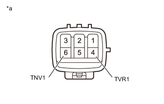
CHECK TERMINAL VOLTAGE (POWER SOURCE OF NO. 1 HYDROGEN TANK ASSEMBLY (TANK SHUT VALVE 1))
-
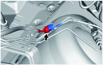
Disconnect the No. 1 hydrogen tank assembly (tank shut valve 1) connector.
-
Turn the power switch on (IG).
-

*a Front view of wire harness connector
(to No. 1 Hydrogen Tank Assembly (Tank Shut Valve 1))
Measure the voltage according to the value(s) in the table below.
Standard Voltage Tester Connection Condition Specified Condition R2-4 (TVR1) - Body ground Power switch on (IG) 11 to 14 V -
Turn the power switch off.
-
Reconnect the No. 1 hydrogen tank assembly (tank shut valve 1) connector.
Result Proceed to OK NG
NG
CHECK HARNESS AND CONNECTOR (NO. 1 HYDROGEN TANK ASSEMBLY (TANK SHUT VALVE 1) - TANK SHUT VALVE RELAY) Click here
OK
-
-
CHECK HARNESS AND CONNECTOR (NO. 1 HYDROGEN TANK ASSEMBLY (TANK SHUT VALVE 1) - HYDROGEN FUEL CONTROL ECU ASSEMBLY)
-
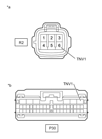
*a Front view of wire harness connector
(to No. 1 Hydrogen Tank Assembly (Tank Shut Valve 1))
*b Front view of wire harness connector
(to Hydrogen Fuel Control ECU Assembly)
Disconnect the No. 1 hydrogen tank assembly (tank shut valve 1) connector.
-
Disconnect the hydrogen fuel control ECU assembly connector.
-
Measure the resistance according to the value(s) in the table below.
Standard Resistance Tester Connection Condition Specified Condition R2-6 (TNV1) - P30-6 (TNV1) Always Below 1 Ω R2-6 (TNV1) or P30-6 (TNV1) -Body ground and other terminals Always 10 kΩ or higher -
Reconnect the hydrogen fuel control ECU assembly connector.
-
Reconnect the No. 1 hydrogen tank assembly (tank shut valve 1) connector.
Result Proceed to OK NG
NG 
REPAIR OR REPLACE HARNESS OR CONNECTOR
OK
-
-
CHECK HARNESS AND CONNECTOR (HYDROGEN FUEL CONTROL ECU ASSEMBLY - BODY GROUND)
-
Disconnect the hydrogen fuel control ECU assembly connector.
-
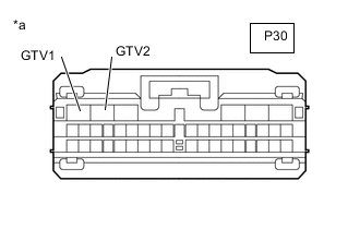
*a Front view of wire harness connector
(to Hydrogen Fuel Control ECU Assembly)
Measure the resistance according to the value(s) in the table below.
Standard Resistance Tester Connection Condition Specified Condition P30-1 (GTV1) - Body ground Always Below 1 Ω P30-2 (GTV2) - Body ground Always Below 1 Ω -
Reconnect the hydrogen fuel control ECU assembly connector.
Result Proceed to OK NG
NG
REPAIR OR REPLACE HARNESS OR CONNECTOR
OK
-
-
CHECK NO. 1 HYDROGEN TANK ASSEMBLY (TANK SHUT VALVE 1)
-
Disconnect the R2 No. 1 hydrogen tank assembly (tank shut valve 1) connector.
-
*a Component without harness connected
(No. 1 Hydrogen Tank Assembly (Tank Shut Valve 1))
Measure the resistance according to the value(s) in the table below.
Standard Resistance Tester Connection Condition Specified Condition 4 (TVR1) - 6 (TNV1) 20°C (68°F) 1.3 to 3.3 Ω 4 (TVR1) or 6 (TNV1) -Body ground and other terminals Always 1 MΩ or higher -
Reconnect the R2 No. 1 hydrogen tank assembly (tank shut valve 1) connector.
Result Proceed to OK NG
OK
REPLACE HYDROGEN FUEL CONTROL ECU ASSEMBLY Click here
NG
REPLACE NO. 1 HYDROGEN TANK ASSEMBLY (TANK SHUT VALVE 1) Click here
-
-
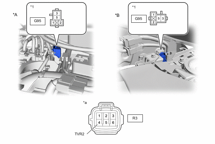
CHECK HARNESS AND CONNECTOR (NO. 1 HYDROGEN TANK ASSEMBLY (TANK SHUT VALVE 1) - TANK SHUT VALVE RELAY)
-
Disconnect the No. 1 hydrogen tank assembly (tank shut valve 1) connector.
-
Disconnect the R3 No. 2 Hydrogen Tank Assembly (Tank Shut Valve 2) connector.
-
Disconnect the P30 hydrogen fuel control ECU assembly connector.
-
Remove the tank shut valve relay.
-
Measure the resistance according to the value(s) in the table below.

*A for LHD *B for RHD *1 Tank Shut Valve Relay Holder - - *a Front view of wire harness connector
(to No. 1 Hydrogen Tank Assembly (Tank Shut Valve 1))
- - Standard Resistance Tester Connection Condition Specified Condition R2-4 (TVR1) - G95-5 (Tank shut valve relay holder) Always Below 1 Ω R2-4 (TVR1) or G95-5 (Tank shut valve relay holder) - Body ground and other terminals Always 10 kΩ or higher -
Reinstall the tank shut valve relay.
-
Reconnect the P30 hydrogen fuel control ECU assembly connector.
-
Reconnect the R3 No. 2 hydrogen tank assembly (tank shut valve 2) connector.
-
Reconnect the No. 1 hydrogen tank assembly (tank shut valve 1) connector.
Result Proceed to OK NG
OK
GO TO STEP 11 Click here
NG
REPAIR OR REPLACE HARNESS OR CONNECTOR
-
-
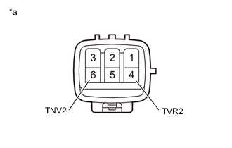
CHECK TERMINAL VOLTAGE (POWER SOURCE OF NO. 2 HYDROGEN TANK ASSEMBLY (TANK SHUT VALVE 2))
-
Disconnect the No. 2 hydrogen tank assembly (tank shut valve 2) connector.
-
Turn the power switch on (IG).
-
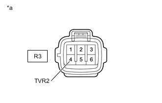
*a Front view of wire harness connector
(to No. 2 Hydrogen Tank Assembly (Tank Shut Valve 2))
Measure the voltage according to the value(s) in the table below.
Standard Voltage Tester Connection Condition Specified Condition R3-4 (TVR2) - Body ground Power switch on (IG) 11 to 14 V -
Turn the power switch off.
-
Reconnect the No. 2 hydrogen tank assembly (tank shut valve 2) connector.
Result Proceed to OK NG
NG
CHECK HARNESS AND CONNECTOR (NO. 2 HYDROGEN TANK ASSEMBLY (TANK SHUT VALVE 2) - TANK SHUT VALVE RELAY) Click here
OK
-
-
CHECK HARNESS AND CONNECTOR (NO. 2 HYDROGEN TANK ASSEMBLY (TANK SHUT VALVE 2) - HYDROGEN FUEL CONTROL ECU ASSEMBLY)
-
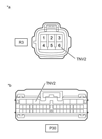
*a Front view of wire harness connector
(to No. 2 Hydrogen Tank Assembly (Tank Shut Valve 2))
*b Front view of wire harness connector
(to Hydrogen Fuel Control ECU Assembly)
Disconnect the No. 2 hydrogen tank assembly (tank shut valve 2) connector.
-
Disconnect the hydrogen fuel control ECU assembly connector.
-
Measure the resistance according to the value(s) in the table below.
Standard Resistance Tester Connection Condition Specified Condition R3-6 (TNV2) - P30-3 (TNV2) Always Below 1 Ω R3-6 (TNV2) or P30-3 (TNV2) -Body ground and other terminals Always 10 kΩ or higher -
Reconnect the hydrogen fuel control ECU assembly connector.
-
Reconnect the No. 2 hydrogen tank assembly (tank shut valve 2) connector.
Result Proceed to OK NG
NG
REPAIR OR REPLACE HARNESS OR CONNECTOR
OK
-
-
CHECK NO. 2 HYDROGEN TANK ASSEMBLY (TANK SHUT VALVE 2)
-
Disconnect the No. 2 hydrogen tank assembly (tank shut valve 2) connector.
-
*a Component without harness connected
(No. 2 Hydrogen Tank Assembly (Tank Shut Valve 2))
Measure the resistance according to the value(s) in the table below.
Standard Resistance Tester Connection Condition Specified Condition 4 (TVR2) - 6 (TNV2) 20°C (68°F) 1.3 to 3.3 Ω 4 (TVR2) or 6 (TNV2) -Body ground and other terminals Always 1 MΩ or higher -
Reconnect the No. 2 hydrogen tank assembly (tank shut valve 2) connector.
Result Proceed to OK NG
OK
REPLACE HYDROGEN FUEL CONTROL ECU ASSEMBLY Click here
NG
REPLACE NO. 2 HYDROGEN TANK ASSEMBLY (TANK SHUT VALVE 2) Click here
-
-
CHECK HARNESS AND CONNECTOR (NO. 2 HYDROGEN TANK ASSEMBLY (TANK SHUT VALVE 2) - TANK SHUT VALVE RELAY)
-
Disconnect the R2 No. 1 hydrogen tank assembly (tank shut valve 1) connector.
-
Disconnect the No. 2 hydrogen tank assembly (tank shut valve 2) connector.
-
Disconnect the P30 hydrogen fuel control ECU assembly connector.
-
Remove the tank shut valve relay.
-
Measure the resistance according to the value(s) in the table below.
*A for LHD *B for RHD *1 Tank Shut Valve Relay Holder - - *a Front view of wire harness connector
(to No. 2 Hydrogen Tank Assembly (Tank Shut Valve 2))
- - Standard Resistance Tester Connection Condition Specified Condition R3-4 (TVR2) - G95-5 (Tank shut valve relay holder) Always Below 1 Ω R3-4 (TVR2) or G95-5 (Tank shut valve relay holder) - Body ground and other terminals Always 10 kΩ or higher -
Reinstall the tank shut valve relay.
-
Reconnect the P30 hydrogen fuel control ECU assembly connector.
-
Reconnect the No. 2 hydrogen tank assembly (tank shut valve 2) connector.
-
Reconnect the R2 No. 1 hydrogen tank assembly (tank shut valve 1) connector.
Result Proceed to OK NG
NG
REPAIR OR REPLACE HARNESS OR CONNECTOR
OK
-
-
CHECK HARNESS AND CONNECTOR (HYDROGEN FUEL CONTROL ECU ASSEMBLY - TANK SHUT VALVE RELAY)
-
Disconnect the R2 No. 1 hydrogen tank assembly (tank shut valve 1) connector.
-
Disconnect the R3 No. 2 hydrogen tank assembly (tank shut valve 2) connector.
-
Disconnect the hydrogen fuel control ECU assembly connector.
-
Remove the tank shut valve relay.
-
Measure the resistance according to the value(s) in the table below.
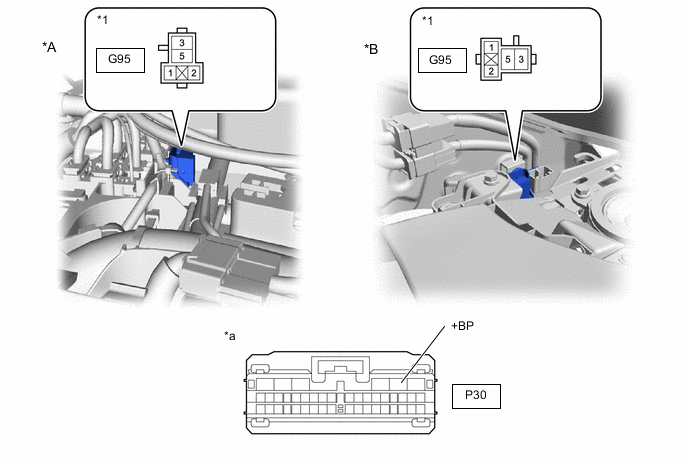
*A for LHD *B for RHD *1 Tank Shut Valve Relay Holder - - *a Front view of wire harness connector
(to Hydrogen Fuel Control ECU Assembly)
- - Standard Resistance Tester Connection Condition Specified Condition P30-5 (+BP) - G95-5 (Tank shut valve relay holder) Always Below 1 Ω P30-5 (+BP) or G95-5 (Tank shut valve relay holder) - Body ground and other terminals Always 10 kΩ or higher -
Reinstall the tank shut valve relay.
-
Reconnect the hydrogen fuel control ECU assembly connector.
-
Reconnect the R3 No. 2 hydrogen tank assembly (tank shut valve 2) connector.
-
Reconnect the R2 No. 1 hydrogen tank assembly (tank shut valve 1) connector.
Result Proceed to OK NG
NG
REPAIR OR REPLACE HARNESS OR CONNECTOR
OK
-
-
INSPECT RELAY (TANK SHUT VALVE RELAY)
Result Proceed to OK NG
NG
REPLACE RELAY (TANK SHUT VALVE RELAY)
OK
-
CHECK TERMINAL VOLTAGE (POWER SOURCE OF TANK SHUT VALVE RELAY)
-
Remove the tank shut valve relay.
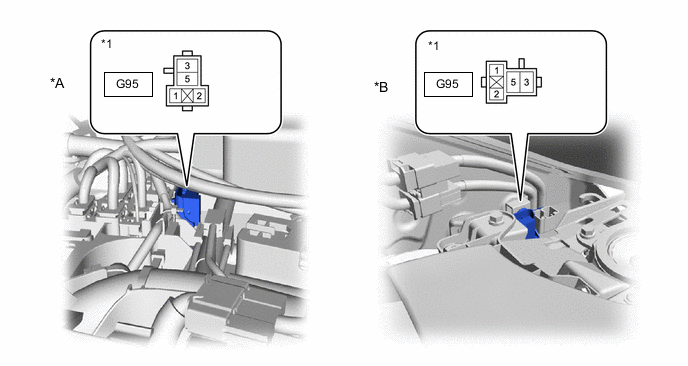
*A for LHD *B for RHD *1 Tank Shut Valve Relay Holder - - -
Measure the voltage according to the value(s) in the table below.
Standard Voltage Tester Connection Condition Specified Condition G95-3 (Tank shut valve relay holder) - Body ground Power switch off 11 to 14 V -
Reinstall the tank shut valve relay.
Result Proceed to OK NG
NG
REPAIR OR REPLACE HARNESS OR CONNECTOR (TANK SHUT VALVE RELAY - AUXILIARY BATTERY)
OK
-
-
CHECK HARNESS AND CONNECTOR (TANK SHUT VALVE RELAY - BODY GROUND)
-
Remove the tank shut valve relay.
-
Measure the resistance according to the value(s) in the table below.
*1 for LHD *2 for RHD *3 Tank Shut Valve Relay Holder - - Standard Resistance Tester Connection Condition Specified Condition G95-2 (Tank shut valve relay holder) - Body ground Always Below 1 Ω -
Reinstall the tank shut valve relay.
Result Proceed to OK NG
NG
REPAIR OR REPLACE HARNESS OR CONNECTOR
OK
-
-
CHECK TERMINAL VOLTAGE (POWER SOURCE OF TANK SHUT VALVE RELAY)
-
Remove the tank shut valve relay.
*1 for LHD *2 for RHD *3 Tank Shut Valve Relay Holder - - -
Turn the power switch on (IG).
-
Measure the voltage according to the value(s) in the table below.
Standard Voltage Tester Connection Condition Specified Condition G95-1 (Tank shut valve relay holder) - Body ground Power switch on (IG) 11 to 14 V -
Turn the power switch off.
-
Reinstall the tank shut valve relay.
Result Proceed to OK NG
OK
CHECK FOR INTERMITTENT PROBLEMS Click here
NG
-
-
CHECK HARNESS AND CONNECTOR (EV CONTROL ECU - TANK SHUT VALVE RELAY)
-
Disconnect the EV control ECU connector.
-
Remove the tank shut valve relay.
-
Measure the resistance according to the value(s) in the table below.
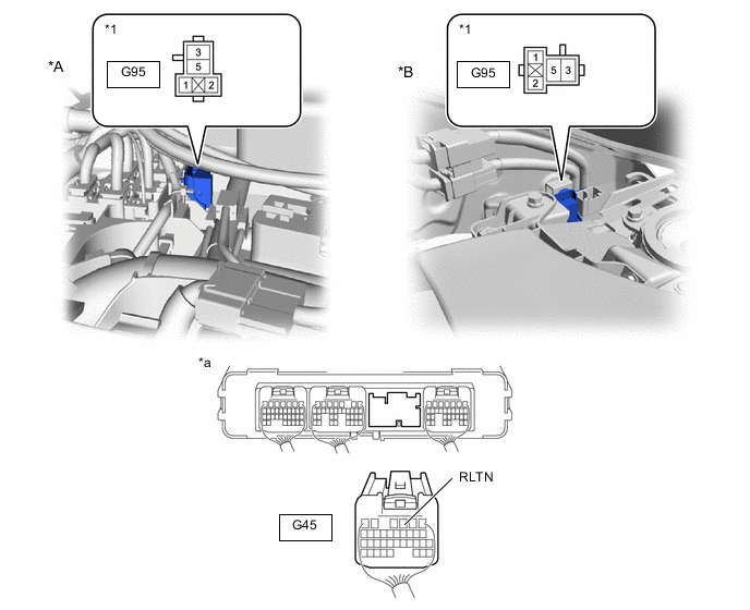
*A for LHD *B for RHD *1 Tank Shut Valve Relay Holder - - *a Rear view of wire harness connector
(to EV Control ECU)
- - Standard Resistance Tester Connection Condition Specified Condition G45-3 (RLTN) - G95-1 (Tank shut valve relay holder) Always Below 1 Ω G45-3 (RLTN) or G95-1 (Tank shut valve relay holder) - Body ground and other terminals Always 10 kΩ or higher -
Reinstall the tank shut valve relay.
-
Reconnect the EV control ECU connector.
Result Proceed to OK NG
OK
REPLACE EV CONTROL ECU Click here
NG
REPAIR OR REPLACE HARNESS OR CONNECTOR
-