FC CONTROL SYSTEM, Diagnostic DTC:P1DEF-450
| DTC Code | DTC Name |
|---|---|
| P1DEF-450 | FC Stack Performance |
DESCRIPTION
The FC stack consists of 370 cells. The amounts of hydrogen and air that are fed into the FC stack, and the FC stack temperature are regulated for stable power generation.
If the cell voltage, which is based on each cell voltage watched by the cell monitor, is abnormally low despite that both hydrogen and air are supplied more than the specified amounts and the cooling system is operating properly, the FC control ECU interprets it as a FC stack malfunction, and sets this DTC.
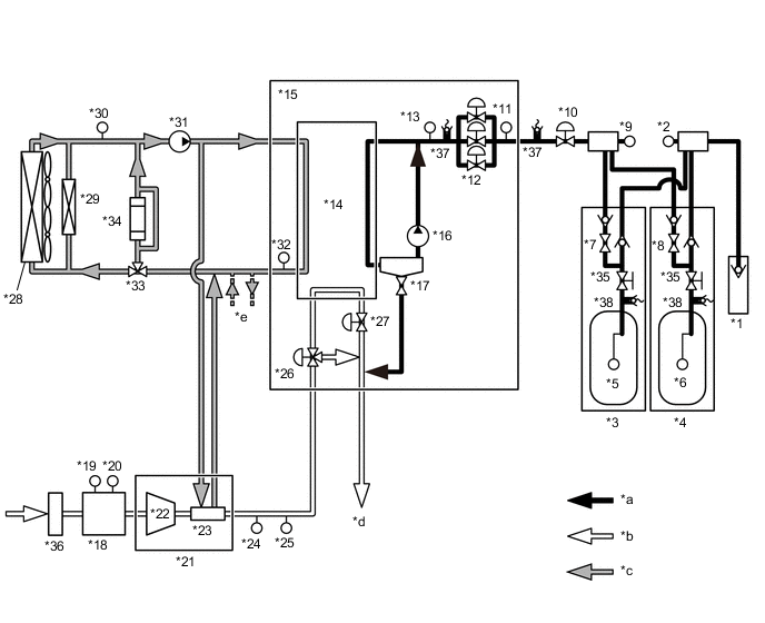
| *1 | Hydrogen Inlet Receptacle Assembly | *2 | Hydrogen Tank Pressure Sensor (for Inlet Side) |
| *3 | No. 1 Hydrogen Tank Assembly | *4 | No. 2 Hydrogen Tank Assembly |
| *5 | Hydrogen Tank Temperature Sensor 1 | *6 | Hydrogen Tank Temperature Sensor 2 |
| *7 | Tank Shut Valve 1 | *8 | Tank Shut Valve 2 |
| *9 | Hydrogen Tank Pressure Sensor (for Outlet Side) | *10 | Hydrogen Supply Regulator Assembly |
| *11 | Medium-range Hydrogen Pressure Sensor | *12 | Hydrogen Injector |
| *13 | Low-range Hydrogen Pressure Sensor | *14 | FC Stack |
| *15 | FC Stack Assembly | *16 | Hydrogen Pump |
| *17 | Exhaust Drainage Valve | *18 | Mass Air Flow Meter |
| *19 | Airflow Sensor | *20 | Intake Air Temperature Sensor |
| *21 | FC Air Compressor with Motor Assembly | *22 | FC Air Compressor |
| *23 | Intercooler | *24 | FC Gas Temperature Sensor |
| *25 | FC Stack Inlet Air Pressure Sensor (Turbo Pressure Sensor) | *26 | Air Shunt Valve |
| *27 | Air Pressure Regulating Valve | *28 | FC Radiator Assembly |
| *29 | Sub-Radiator Assembly | *30 | Water Temperature Sensor (for Radiator Outlet Side) |
| *31 | FC Cooling Water Pump Assembly | *32 | Water Temperature Sensor (for FC Stack Outlet Side) |
| *33 | FC Cooling Water Temperature Control Valve | *34 | FC Cooling Water Ion Exchanger Assembly |
| *35 | Manual Valve | *36 | Air Cleaner Filter Element Sub-assembly |
| *37 | Pressure Relief Valve | *38 | Pressure Relief Device |
| *a | Hydrogen System | *b | Air System |
| *c | Cooling System | *d | To the Exhaust Drainage Pipe |
| *e | To the air conditioning heater circuit | - | - |
| DTC No. | Detection Item | DTC Detection Condition | Trouble Area | Warning Indicate |
|---|---|---|---|---|
| P1DEF-450 | FC Stack Performance | Lowest cell voltage has decreased below a calculated threshold. This malfunction detection is active while the following conditions are met:
(1 trip detection logic) |
|
Master Warning Light: Comes on |
| Vehicle Condition | FC shutdown (power switch on (IG)) |
FC startup process | FC intermittent operation | FC is generating power (vehicle is in stationary) |
FC is generating power (vehicle is traveling) |
FC shutdown process |
|---|---|---|---|---|---|---|
| Data List "FC Mode" |
FC Shutdown | FC Startup Process | FC Working | FC Shutdown Process | ||
| Data List "FC Intermittent Operation" |
OFF | ON | OFF | OFF | ||
| DTC Detection | - | ○ | ○ | ○ | ○ | ○ |
Note
If low quality hydrogen is applied, this DTC may be output.
Tech Tips
By accessing the "FC Mode" and "FC Intermittent Operation" in the freeze frame data, the FC system condition at the time the malfunction occurred can be checked.
| DTC No. | Data List |
|---|---|
| P1DEF-450 |
|
Tech Tips
Refer to the "FC Stack Cell Minimum Voltage" and "FC Stack Cell Average Minimum Voltage" in the Data List when troubleshooting. The cell voltage is normally within approximately 0 to 1 V, and the FC voltage is in a range of approximately between from 222 to 370 V (when the vehicle is stationary and is in modes other than intermittent operation).
The following items can be helpful when performing repairs:
-
Vehicle Speed
-
Shift Sensor Shift Position
-
Accelerator Degree
-
Ready
-
FC Mode
-
FC Intermittent Operation
-
FC Voltage before Boosting
-
FC Current
-
Target Low-range Hydrogen Pressure
-
Smoothed Value of Low-range Hydrogen Pressure
-
Target Hydrogen Pump Revolution
-
Hydrogen Pump Revolution
-
Target FC Stack Air Pressure (FC Stack Inlet)
-
Smoothed Value of FC Stack Air Pressure (FC Stack Inlet)
-
Target Mass Air Flow Value
-
Mass Air Flow Value
-
Target Air Compressor Revolution
-
Air Compressor Revolution
-
Target FC Stack Coolant Temperature (FC Stack Outlet)
-
Smoothed Value of FC Stack Coolant Temperature (FC Stack Outlet)
-
Exhaust Drainage Valve Driving Request
Common Data List items for FC inspection
Tech Tips
This DTC may be output due to malfunctions in the hydrogen, air or cooling systems. If DTCs for those systems are found, troubleshoot them first. In addition, check the freeze frame data and Data List values for the hydrogen pressure, air pressure, airflow volume, and FC stack outlet coolant temperature (less than approximately 75°C (167°F)).
-
Low-range hydrogen pressure:
Compare the "Target Low-range Hydrogen Pressure" and the "Smoothed Value of Low-range Hydrogen Pressure" in the Data List.
-
Medium-range hydrogen pressure:
"Smoothed Value of Medium-range Hydrogen Pressure" is in a range of approximately 1000 to 1600 kPa(abs).
-
Hydrogen pump revolution:
Compare the "Target Hydrogen Pump Revolution" and the "Hydrogen Pump Revolution" in the Data List.
-
Air pressure:
Compare the "Target FC Stack Air Pressure (FC Stack Inlet)" and the "Smoothed Value of FC Stack Air Pressure (FC Stack Inlet)" in the Data List.
-
Airflow volume:
Compare the "Target Mass Air Flow Value" and the "Mass Air Flow Value" in the Data List.
-
Air compressor revolution:
Compare the "Target Air Compressor Revolution" and the "Air Compressor Revolution" in the Data List.
CAUTION / NOTICE / HINT
CAUTION:
-
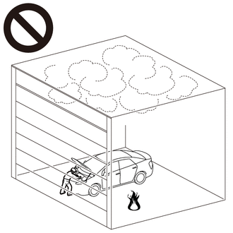
Work procedures must be performed in an area with good ventilation (airflow) where hydrogen gas will not accumulate, and flames or other things that could act as ignition sources must not be present.
-
Accumulated hydrogen gas could ignite, resulting in a serious accident.
Note
When the vehicle is parked with the power switch off, if the FC control ECU judges that the FC stack temperature will go below 0°C (32°F), it activates the FC air compressor, hydrogen pump and FC cooling water pump for a maximum of 180 seconds and drains water from the FC stack assembly. When performing inspection or repairs with the power switch off (not on (IG) or on (READY)), disconnect the cable from the negative (-) auxiliary battery terminal before performing work (If the auxiliary battery voltage is needed to conduct inspection, warm up the FC system beforehand).
Tech Tips
-
Forcing the SOC of the EV battery to decrease by applying electrical loads such as turning on the air conditioning (HOT MAX, maximum airflow), or depressing the accelerator pedal with the shift lever in P, the "FC Intermittent Operation" of the Data List is easily to enter OFF (power generation mode).
After the repair, clear the DTCs and perform the following procedure to check that DTCs are not output.
-
Drive the vehicle for 10 to 20 minutes according to the freeze frame data (Vehicle Speed, Accelerator Degree, etc.).
CAUTION:
Perform this road test only in an appropriate safe location, in accordance with all local laws.
PROCEDURE
-
CHECK DTC OUTPUT
Note
The freeze frame data*1 is cleared when DTCs are cleared. Be sure to make a note of necessary data in advance.
-
Connect the GTS to the DLC3.
-
Turn the power switch on (IG).
-
Turn the GTS on.
-
Enter the following menus: Powertrain / FC / Trouble Codes.
-
Check for DTCs.
Powertrain > FC > Trouble CodesResult Result Proceed to P1DEF-450 only is output, or DTCs except the ones in the table below are also output. A Any of the following DTCs are also output. B Malfunction Content Relevant DTC Microcomputer Malfunction / Power Source Circuit Malfunction P1DCF-450 Cell Monitor Performance Communication System Malfunction P1D5F-450 Lost Communication with Cell Monitor P1D84-450 Lost Communication with Hydrogen Pump Inverter P1DC9-450 Lost Communication with FC Water Pump Inverter P1DF2-450 Hydrogen Pump Inverter Drive Signal Stuck ON P1DF3-450 Hydrogen Pump Inverter Drive Signal Stuck OFF P1DF7-450 FC Water Pump Inverter Drive Signal Stuck ON P1DF8-450 FC Water Pump Inverter Drive Signal Stuck OFF Sensor and Actuator Circuit Malfunction P0100-450 Mass Air Flow Circuit P1D24-450 Hydrogen Pump Speed Control Performance P1D2C-450 FC Stack Coolant Temperature Sensor (FC Stack Outlet) Circuit Low P1D2D-450 FC Stack Coolant Temperature Sensor (FC Stack Outlet) Circuit High P1D2F-450 FC Water Pump Speed Control Performance P1D7F-450 Air Compressor Speed Control Performance P1D92-450 FC Stack Air Pressure Sensor (FC Stack Inlet) Circuit Low P1D93-450 FC Stack Air Pressure Sensor (FC Stack Inlet) Circuit High P1DAC-450 Exhaust Drainage Valve Circuit Low P1DAD-450 Exhaust Drainage Valve Circuit High P1DBC-450 Low-range Hydrogen Pressure Sensor Circuit Low P1DBD-450 Low-range Hydrogen Pressure Sensor Circuit High P1E22-450 Air Pressure Regulating Valve Phase A Circuit Low P1E23-450 Air Pressure Regulating Valve Phase A Circuit High P1E27-450 Air Pressure Regulating Valve Phase B Circuit Low P1E28-450 Air Pressure Regulating Valve Phase B Circuit High P1E2C-450 Air Shunt Valve Phase A Circuit Low P1E2D-450 Air Shunt Valve Phase A Circuit High P1E32-450 Air Shunt Valve Phase B Circuit Low P1E33-450 Air Shunt Valve Phase B Circuit High P1E47-450 FC Stack Coolant Temperature Sensor (FC Stack Outlet / Radiator Outlet)Correlation P1E48-450 Barometric Pressure Sensor / FC Stack Air Pressure Sensor (FC Stack Inlet)Correlation System Malfunction P0101-450 Mass Air Flow Circuit Range/Performance P1D83-450 Hydrogen Pump Inverter Performance P1D91-450 Air Control System Performance P1DC0-450 Low-range Hydrogen Pressure Too Low P1DC5-450 Air Pressure Too High P1DC8-450 FC Water Pump Inverter Performance P1DE4-450 FC Coolant Water Temperature Malfunction Tech Tips
-
DTC P1DEF-450 may be set due to problems that cause the DTCs shown above to be output. If such happens, troubleshoot the suspected area(s) corresponding to the output DTC(s) in order of the listed DTCs shown in the table above.
-
*1: The "FC Stack Cell Minimum Voltage" or "FC Stack Cell Average Minimum Voltage" may have been below approximately 0 V. While the FC stack is warmed up in quick mode when the FC system is cold, the cell voltage may decrease even if the FC system is normal.
-
-
Turn the power switch off.
B 
GO TO DTC CHART Click here
A 
-
-
CHECK VEHICLE CONTROL HISTORY
-
Connect the GTS to the DLC3.
-
Turn the power switch on (IG).
-
Turn the GTS on.
-
Enter the following menus: Powertrain / FC / Utility / Vehicle Control History.
Powertrain > FC > UtilityTester Display Vehicle Control History -
Check Vehicle Control History.
FFD Group Code Techstream Display Possible Cause Action to be Taken 01 X3120 FC Stack Power Generation
Canceled by Poor Drainage
-
Poor drainage from FC stack due to leaving the vehicle in READY ON continuously in a location where the vehicle was tilted significantly to the side
Explain the customer that leaving the vehicle in READY ON in a location with a large sideways tilt caused the system to detect "poor drainage", resulting in FC system shutdown.
After moving the vehicle to a flat location, stopping the vehicle in a horizontal orientation and waiting for approximately 5 minutes or more, the FC system can be started.
After starting the FC system, press the FC water release switch to perform forced drainage.
Tech Tips
-
By checking the Data List, Freeze Frame Data or Vehicle Control History Freeze Frame Data item "Vehicle Tilt Angle (Horizontal Direction)", the tilt angle of the vehicle in the lateral (left-right) direction can be checked.
-
Leaving the vehicle in READY ON in a location with a large lateral tilt (vehicle is tilted approximately 15° or more to the left or right) may cause the FC system to stop.
-
If the vehicle control history item "FC Stack Power Generation Canceled by Poor Drainage" is stored, explain to the customer that they should avoid leaving the vehicle in READY ON for a long time (approximately 20 minutes or more) in a location where the vehicle has a large sideways tilt.
Result Result Proceed to Vehicle control history item "FC Stack Power Generation Canceled by Poor Drainage" is output A Vehicle control history item "FC Stack Power Generation Canceled by Poor Drainage" is not output B -
-
Clear the Vehicle Control History.
B 
CHECK EXHAUST HYDROGEN GAS Click here
A
-
-
PERFORM FORCED DRAINAGE
-
Move the vehicle to a flat location and ensure the vehicle is not tilted.
-
After the wait for 5 minutes or more with power switch off, turn the power switch on (READY).
-
Operate the FC water release switch to perform forced drainage.
Result Proceed to NEXT
NEXT
-
-
CLEAR DTC
-
Connect the GTS to the DLC3.
-
Turn the power switch on (IG).
-
Turn the GTS on.
-
Enter the following menus: Powertrain / FC / Trouble Codes.
-
Clear the DTCs.
Powertrain > FC > Clear DTCs -
Turn the power switch off and wait for 5 minutes or more.
Result Proceed to NEXT
NEXT
-
-
SIMULATION TEST
-
Connect the GTS to the DLC3.
-
Turn the power switch on (IG).
-
Turn the GTS on.
-
Drive the vehicle for 10 to 20 minutes according to the freeze frame data (Vehicle Speed, Accelerator Degree, etc.).
If vehicle speeds, accelerator pedal positions, road conditions, ambient temperatures and climates at the time the malfunction occurred can be confirmed, take them into account.
CAUTION:
Perform this road test only in an appropriate safe location, in accordance with all local traffic laws.
-
Enter the following menus: Powertrain / FC / Trouble Codes.
-
Check for DTCs.
Powertrain > FC > Trouble CodesResult Result Proceed to DTCs are not output A DTC P1DEF-450 is output B -
Turn the power switch off.
A
END
B
-
-
CHECK EXHAUST HYDROGEN GAS
CAUTION:
-
Work procedures must be performed in an area with good ventilation (airflow) where hydrogen gas will not accumulate, and flames or other things that could act as ignition sources must not be present.
-
Accumulated hydrogen gas could ignite, resulting in a serious accident.
-
Ensure the safety of the areas in front and at the back of the vehicle.
-
Put wheel chocks and securely apply the parking brake.
-
Connect the GTS to the DLC3.
-
Turn the power switch on (IG).
-
Turn the GTS on.
-
Enter the following menus: Powertrain / FC / Data List / FC Mode, FC Intermittent Operation, Exhaust Drainage Valve Driving Request
Powertrain > FC > Data ListTester Display FC Mode FC Intermittent Operation Exhaust Drainage Valve Driving Request -
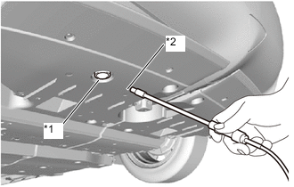
*1 Tailpipe *2 Hydrogen gas detector probe Using a hydrogen gas detector, measure the hydrogen concentration in the gas emitted from the tail pipe.
Note
-
Perform this measurement in an environment where there is no wind.
-
Position the hydrogen gas detector probe in an area 100 mm (3.94 in.) away from the tailpipe opening. (Avoid locations underneath the tailpipe opening)
-
Position the hydrogen gas detector probe so that it is free from dropping water that comes from the tailpipe opening.
-
-
Measure the hydrogen concentration for 1 minute with the shift lever in P, the power switch on (READY), the Data List "FC Mode" showing FC Working and "FC Intermittent Operation" showing OFF. Watch for changes in the concentration when the "Exhaust Drainage Valve Driving Request" is ON and OFF in the Data List.
Note
Start measurement immediately after the power switch is turned on (READY).
-
Turn the power switch off.
Result Result Proceed to Hydrogen concentration increases when the "Exhaust Drainage Valve Driving Request" is ON but does not increase when it is OFF. A Other than above* B
-
*: The exhaust drainage valve is malfunctioning
-
Exhaust drainage valve is stuck closed:
-
Regardless of the "Exhaust Drainage Valve Driving Request" being ON or OFF, the concentration shown on the hydrogen gas detector has remained low.
-
Exhaust drainage valve is stuck open:
-
Regardless of the "Exhaust Drainage Valve Driving Request" being ON or OFF, the concentration shown on the hydrogen gas detector has remained high when the power switch is on (READY).
-
B
REPLACE FC STACK ASSEMBLY Click here
A
-
-
CHECK AIR CLEANER FILTER ELEMENT SUB-ASSEMBLY
-
Check that the air cleaner filter element sub-assembly is not clogged.
OK The air cleaner filter element sub-assembly is not clogged Result Proceed to OK NG
OK
GO TO STEP 9 Click here
NG
-
-
CLEAN OR REPLACE AIR CLEANER FILTER ELEMENT SUB-ASSEMBLY
-
Clean or replace the air cleaner filter element sub-assembly.
Result Proceed to NEXT
NEXT
-
-
CHECK INTAKE AND EXHAUST PIPING
-
Check that no air comes in without flowing through each part of the intake air system and the exhaust drainage pipe is not clogged, disconnected, or damaged.
OK The intake and exhaust piping is not clogged, disconnected or damaged Result Proceed to OK NG
OK
GO TO STEP 11 Click here
NG
-
-
REPAIR OR REPLACE MALFUNCTIONING PARTS
Result Proceed to NEXT
NEXT
-
CLEAR DTC
-
Connect the GTS to the DLC3.
-
Turn the power switch on (IG).
-
Turn the GTS on.
-
Enter the following menus: Powertrain / FC / Trouble Codes.
-
Clear the DTCs.
Powertrain > FC > Clear DTCs -
Turn the power switch off and wait for 3 minutes or more.
Result Proceed to NEXT
NEXT
-
-
SIMULATION TEST
-
Connect the GTS to the DLC3.
-
Turn the power switch on (IG).
-
Turn the GTS on.
-
Drive the vehicle for 10 to 20 minutes according to the freeze frame data (Vehicle Speed, Accelerator Degree, etc.).
If vehicle speeds, accelerator pedal positions, road conditions, ambient temperatures and climates at the time the malfunction occurred can be confirmed, take them into account.
CAUTION:
Perform this road test only in an appropriate safe location, in accordance with all local traffic laws.
-
Enter the following menus: Powertrain / FC / Trouble Codes.
-
Check for DTCs.
Powertrain > FC > Trouble CodesResult Result Proceed to DTCs are not output A DTC P1DEF-450 is output B Note
If low quality compressed hydrogen is applied, this DTC may be output.
-
Turn the power switch off.
A
CHECK FOR INTERMITTENT PROBLEMS Click here
B
REPLACE FC STACK ASSEMBLY Click here
-