FC CONTROL SYSTEM, Diagnostic DTC:P1DE4-450
| DTC Code | DTC Name |
|---|---|
| P1DE4-450 | FC Coolant Water Temperature Malfunction |
DESCRIPTION
The cooling system of the FC system controls the FC stack temperature so that it can remain at optimum for power generation. The cooling system employs the FC cooling water pump assembly to feed the FC stack with a necessary amount of FC stack coolant so that the FC stack temperature can remain at an appropriate level, and it forces a heated FC stack coolant at the FC stack outlet to flow into the radiator, cooling down and recirculating the FC stack coolant.
If a control failure that indicates a loss of cooling function has occurred due to malfunctions of the FC cooling water temperature control valve or a clogged radiator, the FC control ECU will set this DTC.
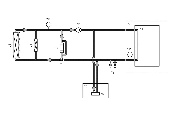
| *1 | FC Stack | *2 | FC Stack Assembly |
| *3 | FC Cooling Water Pump Assembly | *4 | FC Cooling Water Temperature Control Valve |
| *5 | FC Radiator Assembly | *6 | Sub-Radiator Assembly |
| *7 | FC Cooling Water Ion Exchanger Assembly | *8 | FC Air Compressor with Motor Assembly |
| *9 | Intercooler | *10 | Water Temperature Sensor (for Radiator Outlet Side) |
| *11 | Water Temperature Sensor (for FC Stack Outlet Side) | - | - |
| *a | To the air conditioning heater circuit | - | - |
| DTC No. | Detection Item | DTC Detection Condition | Trouble Area | Warning Indicate |
|---|---|---|---|---|
| P1DE4-450 | FC Coolant Water Temperature Malfunction |
|
|
Master Warning Light: Comes on |
Tech Tips
-
This DTC indicates an insufficient amount of FC stack coolant, FC stack coolant leaks, or malfunctions in the FC cooling water temperature control valve or in the cooling fan controller with motor. If a coolant temperature increases high, the FC system output will be limited.
-
If the FC stack coolant volume decreases, the power consumption of the FC cooling water pump assembly is reduced.
| Vehicle Condition | FC shutdown (power switch on (IG)) |
FC startup process | FC intermittent operation | FC is generating power (vehicle is in stationary) |
FC is generating power (vehicle is traveling) |
FC shutdown process |
|---|---|---|---|---|---|---|
| Data List "FC Mode" |
FC Shutdown | FC Startup Process | FC Working | FC Shutdown Process | ||
| Data List "FC Intermittent Operation" |
OFF | ON | OFF | OFF | ||
| DTC Detection | - | - | - | - | ○ | - |
Tech Tips
By accessing the "FC Mode" and "FC Intermittent Operation" in the freeze frame data, the FC system condition at the time the malfunction occurred can be checked.
| DTC No. | Data List |
|---|---|
| P1DE4-450 |
|
The following items can be helpful when performing repairs:
-
Target Radiator Rotary Valve Position
-
FC Water Pump Revolution
-
FC Water Pump Consumption Power
-
Radiator Fan 1 Driving Request
-
Radiator Fan 2 Driving Request
Data List
-
Vehicle Speed
-
Shift Sensor Shift Position
-
Accelerator Degree
-
Ready
-
FC Mode
-
FC Intermittent Operation
-
FC Voltage before Boosting
-
FC Current
-
Target Low-range Hydrogen Pressure
-
Smoothed Value of Low-range Hydrogen Pressure
-
Target Hydrogen Pump Revolution
-
Hydrogen Pump Revolution
-
Target FC Stack Air Pressure (FC Stack Inlet)
-
Smoothed Value of FC Stack Air Pressure (FC Stack Inlet)
-
Target Mass Air Flow Value
-
Mass Air Flow Value
-
Target Air Compressor Revolution
-
Air Compressor Revolution
-
Target FC Stack Coolant Temperature (FC Stack Outlet)
Common Data List items for FC inspection
| DTC No. | Active Test |
|---|---|
| P1DE4-450 |
|
CAUTION / NOTICE / HINT
Note
When the vehicle is parked with the power switch off, if the FC control ECU judges that the FC stack temperature will go below 0°C (32°F), it activates the FC air compressor, hydrogen pump and FC cooling water pump for a maximum of 180 seconds and drains water from the FC stack assembly. When performing inspection or repairs with the power switch off (not on (IG) or on (READY)), disconnect the cable from the negative (-) auxiliary battery terminal before performing work (If the auxiliary battery voltage is needed to conduct inspection, warm up the FC system beforehand).
Tech Tips
-
Forcing the SOC of the EV battery to decrease by applying electrical loads such as turning on the air conditioning (HOT MAX, maximum airflow), or depressing the accelerator pedal with the shift lever in P, the "FC Intermittent Operation" of the Data List is easily to enter OFF (power generation mode).
After the repair, clear the DTCs and perform the following procedure to check that DTCs are not output.
-
Drive the vehicle for 10 minutes according to the freeze frame data (Vehicle Speed, Accelerator Degree).
CAUTION:
Perform this road test only in an appropriate safe location, in accordance with all local laws.
PROCEDURE
-
CHECK DTC OUTPUT
Note
The freeze frame data is cleared when DTCs are cleared. Be sure to make a note of necessary data in advance.
-
Connect the GTS to the DLC3.
-
Turn the power switch on (IG).
-
Turn the GTS on.
-
Enter the following menus: Powertrain / FC / Trouble Codes.
-
Check for DTCs.
Powertrain > FC > Trouble CodesResult Result Proceed to P1DE4-450 only is output, or DTCs except the ones in the table below are also output. A Any of the following DTCs are also output. B Malfunction Content Relevant DTC Communication System Malfunction P1DC9-450 Lost Communication with FC Water Pump Inverter P1DF7-450 FC Water Pump Inverter Drive Signal Stuck ON P1DF8-450 FC Water Pump Inverter Drive Signal Stuck OFF Sensor and Actuator Circuit Malfunction P1D2F-450 FC Water Pump Speed Control Performance P1DD5-450 Radiator Rotary Valve Circuit P1E47-450 FC Stack Coolant Temperature Sensor (FC Stack Outlet / Radiator Outlet)Correlation System Malfunction P1DC8-450 FC Water Pump Inverter Performance Tech Tips
DTC P1DE4-450 may be set due to problems that cause the DTCs shown above to output. If such happens, troubleshoot the suspected area(s) corresponding to the output DTC(s) in order of the listed DTCs shown in the table above.
-
Turn the power switch off.
B 
GO TO DTC CHART Click here
A 
-
-
CLEAR DTC
-
Connect the GTS to the DLC3.
-
Turn the power switch on (IG).
-
Turn the GTS on.
-
Enter the following menus: Powertrain / FC / Trouble Codes.
-
Clear the DTCs.
Powertrain > FC > Clear DTCs -
Turn the power switch off and wait for 3 minutes or more.
Result Proceed to NEXT
NEXT
-
-
CHECK VEHICLE CONDITION
-
Make sure that the front side of the radiator grille is not blocked with anything.
-
Ask the customer if the front side of the radiator grille was blocked with anything.
Result Result Proceed to Not blocked. A Is/was blocked. B Tech Tips
If the radiator grille is blocked, the FC coolant temperature will increase and this DTC may be stored.
B
IF EQUIPPED, EXPLAIN TO CUSTOMER THAT OPTIONAL COMPONENTS WILL BE REMOVED
A
-
-
CHECK RADIATOR ASSEMBLY
-
Check that the radiator core is not clogged, deformed or damaged.
OK Radiator core is not clogged, deformed or damaged. Result Proceed to OK NG
NG
REPAIR OR REPLACE RADIATOR ASSEMBLY
OK
-
-
CHECK COOLANT (FC STACK COOLANT) LEAK
-
Check the FC stack coolant level in the FC radiator reserve tank.
-
Check for FC coolant leaks.
Result Result Proceed to No leaks are found and the FC coolant level in the FC radiator reserve tank is above the low line. A No leaks are found and the FC coolant level in the FC radiator reserve tank is below the low line. B FC coolant leaks are evident. C Tech Tips
-
After repairing the FC coolant leaks and adding coolant, perform the "FC Water Pump", "Radiator Fan1" and "Radiator Fan2" Active Test (FC Active Test item) and make sure that there are no malfunctions.
-
If FC stack coolant leaks are not found despite that the remaining FC stack coolant in the radiator reserve tank is below the Low level, leakage may have occurred inside the FC stack (this may cause the EV control ECU to set DTC P0AA6-485).
-
B
ADD FC STACK COOLANT
C
INSPECT COOLANT LEAK AND ADD COOLANT
A
-
-
CHECK COOLANT HOSE
-
Check that the cooling system hoses are not kinked or clogged.
OK The cooling system hoses are not kinked or clogged Result Proceed to OK NG
NG
REPAIR OR REPLACE COOLANT HOSE
OK
-
-
PERFORM ACTIVE TEST USING GTS (RADIATOR FAN1, RADIATOR FAN2)
-
Connect the GTS to the DLC3.
-
Turn the power switch on (IG).
-
Enter the following menus: Powertrain / FC / Active Test / Radiator Fan1, Radiator Fan2
Powertrain > FC > Active TestTester Display Radiator Fan1
Powertrain > FC > Active TestTester Display Radiator Fan2 -
Perform the Active Test.
OK The cooling fan rotates -
Turn the power switch off.
Result Proceed to OK NG
NG
GO TO COOLING FAN SYSTEM Click here
OK
-
-
PERFORM ACTIVE TEST USING GTS (RADIATOR ROTARY VALVE)
-
Connect the GTS to the DLC3.
-
Turn the GTS on.
-
Drive in city streets for approximately 10 minutes to warm up.
Tech Tips
Raise the "Smoothed Value of FC Stack Coolant Temperature (FC Stack Outlet)" in the Data List to approximately 60°C (140°F)
-
Enter the following menus: Powertrain / FC / Active Test / Radiator Rotary Valve (1)
-
Select "FC Mode", "FC Intermittent Operation", "Radiator Fan 1 Driving Request", "Radiator Fan 2 Driving Request", "Smoothed Value of FC Stack Coolant Temperature (FC Stack Outlet)", "Smoothed Value of FC Stack Coolant Temperature (Radiator Outlet)" and "Target Radiator Rotary Valve Position" in the Data List.
Powertrain > FC > Active TestActive Test Display Radiator Rotary Valve Data List Display FC Mode FC Intermittent Operation Radiator Fan 1 Driving Request Radiator Fan 2 Driving Request Smoothed Value of FC Stack Coolant Temperature (FC Stack Outlet) Smoothed Value of FC Stack Coolant Temperature (Radiator Outlet) Target Radiator Rotary Valve Position -
Turn the power switch on (READY) with the shift lever in P, and check the Data List that "FC Mode" is FC Working and "FC Intermittent Operation" is OFF.
-
Using Active Tests, set the "Radiator Rotary Valve" to 0%.
-
Turn the air conditioning on (Lo/COOL MAX, maximum airflow) to actuate the cooling fan of the FC radiator assembly.
-
Check changes in the "Smoothed Value of FC Stack Coolant Temperature (Radiator Outlet)" in the Data List for 1 minute.
Note
If the "Smoothed Value of FC Stack Coolant Temperature (FC Stack Outlet)" is above 70°C (158°F), perform the operations instructed below to cool it down to approximately 60°C (140°F), and perform the procedure from step (1) again. If the temperature does not decrease, it is suspected that the FC cooling water temperature control valve is malfunctioning.
-
Using Active Tests, set the "Radiator Rotary Valve" to 100%.
-
Turn the air conditioning on to actuate the cooling fan of the FC radiator assembly, allowing the "Smoothed Value of FC Stack Coolant Temperature (FC Stack Outlet)" to decrease to approximately 60°C (140°F).
Tech Tips
-
In order to actuate the FC cooling water pump assembly, put the shift lever in P and turn the power switch on (READY) so that the "FC Mode" and "FC Intermittent Operation" in the Data List is in FC Working and OFF respectively.
-
If the Active Test "Radiator Rotary Valve" is set to 0%, the FC stack coolant begins circulating without bypassing the FC radiator assembly. Thus, even though the cooling fan is switched between ON and OFF, the "Smoothed Value of FC Stack Coolant Temperature (Radiator Outlet)" does not vary virtually.
-
-
Turn the air conditioning off to stop the cooling fan of the FC radiator assembly.
-
Using Active Tests, set the "Radiator Rotary Valve" to 100%.
-
Turn the air conditioning on (Lo/COOL MAX, maximum airflow) to actuate the cooling fan of the FC radiator assembly.
-
Check changes in the "Smoothed Value of FC Stack Coolant Temperature (Radiator Outlet)" in the Data List for 1 minute.
Tech Tips
-
In order to actuate the FC cooling water pump assembly, put the shift lever in P and turn the power switch on (READY) so that the "FC Mode" and "FC Intermittent Operation" in the Data List is in FC Working and OFF respectively.
-
If the Active Test "Radiator Rotary Valve" is set to 100%, the FC stack coolant begins circulating through the radiator assembly. For that reason, the "Smoothed Value of FC Stack Coolant Temperature (Radiator Outlet)" decreases when the cooling fan is actuated.
Figure 1. Reference example (Shift lever in P, and the air conditioning is switched between ON and OFF)
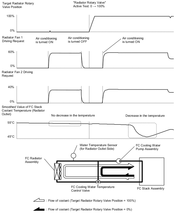
Result Result Proceed to Both following conditions 1 and 2 are met:
-
When the "Target Radiator Rotary Valve Position" is 0%, a decrease in the "Smoothed Value of FC Stack Coolant Temperature (Radiator Outlet)" is less than 2°C (36°F) if the air conditioning is turned from OFF to ON
-
When the "Target Radiator Rotary Valve Position" is 100%, a decrease in the "Smoothed Value of FC Stack Coolant Temperature (Radiator Outlet)" is 2°C (36°F) or more if the air conditioning is turned from OFF to ON
A Other than above B -
-
Turn the power switch off.
A
CHECK FOR INTERMITTENT PROBLEMS Click here
B
REPLACE FC COOLING WATER TEMPERATURE CONTROL VALVE Click here
-