FC CONTROL SYSTEM, Diagnostic DTC:P1DD5-450
| DTC Code | DTC Name |
|---|---|
| P1DD5-450 | Radiator Rotary Valve Circuit |
DESCRIPTION
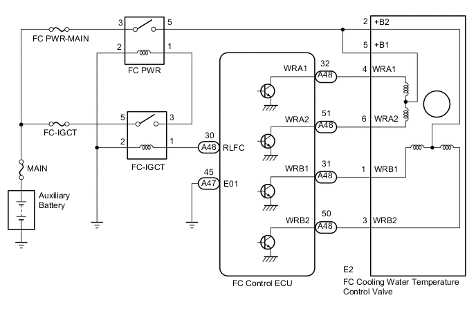
The FC control ECU regulates the FC cooling water temperature control valve so as to maintain the FC stack coolant temperature at a specified level. In order to obtain an appropriate FC stack coolant temperature for the FC stack power generation, the FC control ECU switches the direction of the coolant passage to the bypass side if the FC stack coolant temperature is below a target temperature, or to the radiator if the temperature is above a target.
| DTC No. | Detection Item | DTC Detection Condition | Trouble Area | Warning Indicate |
|---|---|---|---|---|
| P1DD5-450 | Radiator Rotary Valve Circuit | While the FC Mode is in FC Working and each of the 4 terminals of the FC cooling water temperature control valve step motor is OFF, an error has occurred for more than 1 second. (1 trip detection logic) |
|
Master Warning Light: Comes on |
| Vehicle Condition | FC shutdown (power switch on (IG)) |
FC startup process | FC intermittent operation | FC is generating power (vehicle is in stationary) |
FC is generating power (vehicle is traveling) |
FC shutdown process |
|---|---|---|---|---|---|---|
| Data List "FC Mode" |
FC Shutdown | FC Startup Process | FC Working | FC Shutdown Process | ||
| Data List "FC Intermittent Operation" |
OFF | ON | OFF | OFF | ||
| DTC Detection | - | - | ○ | ○ | ○ | - |
Tech Tips
By accessing the "FC Mode" and "FC Intermittent Operation" in the freeze frame data, the FC system condition at the time the malfunction occurred can be checked.
| DTC No. | Data List |
|---|---|
| P1DD5-450 | Estimated Radiator Rotary Valve Position |
| DTC No. | Active Test |
|---|---|
| P1DD5-450 | Radiator Rotary Valve |
WIRING DIAGRAM
CAUTION / NOTICE / HINT
Note
-
Inspect the fuses of circuits related to this system before performing the following procedure.
-
When the vehicle is parked with the power switch off, if the FC control ECU judges that the FC stack temperature will go below 0°C (32°F), it activates the FC air compressor, hydrogen pump and FC cooling water pump for a maximum of 180 seconds and drains water from the FC stack assembly. When performing inspection or repairs with the power switch off (not on (IG) or on (READY)), disconnect the cable from the negative (-) auxiliary battery terminal before performing work (If the auxiliary battery voltage is needed to conduct inspection, warm up the FC system beforehand).
Tech Tips
After the repair, clear the DTCs and perform the following procedure to check that DTCs are not output.
-
Connect the GTS to the DLC3.
-
Turn the power switch on (IG).
-
Turn the power switch on (READY) with the shift lever in P.
-
Enter the following menus: Powertrain / FC / Active Test / Radiator Rotary Valve
-
Perform the Active Test (switching between 0% and 100%).
PROCEDURE
-
CHECK TERMINAL VOLTAGE (POWER SOURCE OF FC COOLING WATER TEMPERATURE CONTROL VALVE)
-
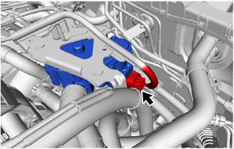
Disconnect the FC cooling water temperature control valve connector.
-
Turn the power switch on (IG).
-
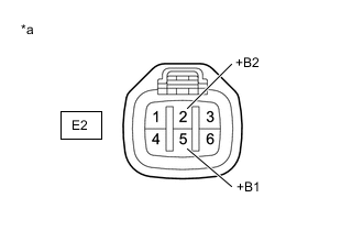
*a Front view of wire harness connector
(to FC Cooling Water Temperature Control Valve)
Measure the voltage according to the value(s) in the table below.
Standard Voltage Tester Connection Condition Specified Condition E2-5 (+B1) or E2-2 (+B2) - Body ground Power switch on (IG) 11 to 14 V -
Turn the power switch off.
-
Reconnect the FC cooling water temperature control valve connector.
Result Proceed to OK NG
NG 
CHECK HARNESS AND CONNECTOR (FC COOLING WATER TEMPERATURE CONTROL VALVE - FC PWR RELAY) Click here
OK 
-
-
CHECK HARNESS AND CONNECTOR (FC CONTROL ECU - FC COOLING WATER TEMPERATURE CONTROL VALVE)
-
Disconnect the FC control ECU connector.
-
Disconnect the FC cooling water temperature control valve connector.
-
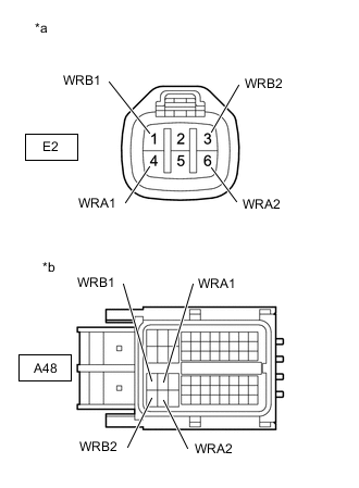
*a Front view of wire harness connector
(to FC Cooling Water Temperature Control Valve)
*b Front view of wire harness connector
(to FC Control ECU)
Measure the resistance according to the value(s) in the table below.
Standard Resistance Tester Connection Condition Specified Condition A48-32 (WRA1) - E2-4 (WRA1) Always Below 1 Ω A48-51 (WRA2) - E2-6 (WRA2) Always Below 1 Ω A48-31 (WRB1) - E2-1 (WRB1) Always Below 1 Ω A48-50 (WRB2) - E2-3 (WRB2) Always Below 1 Ω A48-32 (WRA1) or E2-4 (WRA1) - Body ground and other terminals Always 10 kΩ or higher A48-51 (WRA2) or E2-6 (WRA2) - Body ground and other terminals Always 10 kΩ or higher A48-31 (WRB1) or E2-1 (WRB1) - Body ground and other terminals Always 10 kΩ or higher A48-50 (WRB2) or E2-3 (WRB2) - Body ground and other terminals Always 10 kΩ or higher -
Reconnect the FC cooling water temperature control valve connector.
-
Reconnect the FC control ECU connector.
Result Proceed to OK NG
NG 
REPAIR OR REPLACE HARNESS OR CONNECTOR
OK
-
-
INSPECT FC COOLING WATER TEMPERATURE CONTROL VALVE
Result Proceed to OK NG
NG
REPLACE FC COOLING WATER TEMPERATURE CONTROL VALVE Click here
OK
-
CHECK HARNESS AND CONNECTOR (FC CONTROL ECU - BODY GROUND)
-
Disconnect the FC control ECU connector.
-
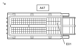
*a Front view of wire harness connector
(to FC Control ECU)
Measure the resistance according to the value(s) in the table below.
Standard Resistance Tester Connection Condition Specified Condition A47-45 (E01) - Body ground Always Below 1 Ω -
Reconnect the FC control ECU connector.
Result Proceed to OK NG
OK
REPLACE FC CONTROL ECU Click here
NG
REPAIR OR REPLACE HARNESS OR CONNECTOR
-
-
CHECK HARNESS AND CONNECTOR (FC COOLING WATER TEMPERATURE CONTROL VALVE - FC PWR RELAY)
-
Disconnect the FC control ECU connector.
-
Remove the FC PWR relay from the motor compartment relay block.
-
Measure the resistance according to the value(s) in the table below.
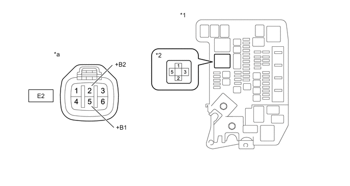
*1 Motor Compartment Relay Block *2 FC PWR Relay Holder *a Front view of wire harness connector
(to FC Cooling Water Temperature Control Valve)
- - Standard Resistance Tester Connection Condition Specified Condition E2-5 (+B1) or E2-2 (+B2) - 5 (FC PWR relay holder) Always Below 1 Ω E2-5 (+B1), E2-2 (+B2) or 5 (FC PWR relay holder) - Body ground and other terminals Always 10 kΩ or higher -
Reinstall the FC PWR relay.
-
Reconnect the FC control ECU connector.
Result Proceed to OK NG
NG
REPAIR OR REPLACE HARNESS OR CONNECTOR
OK
-
-
CHECK TERMINAL VOLTAGE (POWER SOURCE OF FC PWR RELAY)
-

*1 Motor Compartment Relay Block *2 FC PWR Relay Holder Remove the FC PWR relay from the motor compartment relay block.
-
Turn the power switch on (IG).
-
Measure the voltage according to the value(s) in the table below.
Standard Voltage Tester Connection Condition Specified Condition 1 (FC PWR relay holder) - Body ground Power switch on (IG) 11 to 14 V -
Turn the power switch off.
-
Reinstall the FC PWR relay.
Result Proceed to OK NG
NG
CHECK HARNESS AND CONNECTOR (FC-IGCT RELAY - FC PWR RELAY) Click here
OK
-
-
INSPECT RELAY (FC PWR)
Result Proceed to OK NG
NG
REPLACE RELAY (FC PWR)
OK
-
CHECK TERMINAL VOLTAGE (POWER SOURCE OF FC PWR RELAY)
-
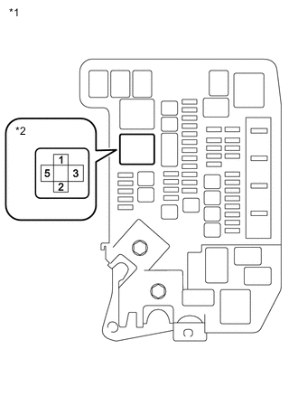
*1 Motor Compartment Relay Block *2 FC PWR Relay Holder Remove the FC PWR relay from the motor compartment relay block.
-
Measure the voltage according to the value(s) in the table below.
Standard Voltage Tester Connection Condition Specified Condition 3 (FC PWR relay holder) - Body ground Power switch off 11 to 14 V -
Reinstall the FC PWR relay.
Result Proceed to OK NG
NG
REPAIR OR REPLACE HARNESS OR CONNECTOR (FC PWR RELAY - AUXILIARY BATTERY)
OK
-
-
CHECK HARNESS AND CONNECTOR (FC PWR RELAY - BODY GROUND)
-
Remove the FC PWR relay from the motor compartment relay block.
-

*1 Motor Compartment Relay Block *2 FC PWR Relay Holder Measure the resistance according to the value(s) in the table below.
Standard Resistance Tester Connection Condition Specified Condition 2 (FC PWR relay holder) - Body ground Always Below 1 Ω -
Reinstall the FC PWR relay.
Result Proceed to OK NG
OK
CHECK FOR INTERMITTENT PROBLEMS Click here
NG
REPAIR OR REPLACE HARNESS OR CONNECTOR
-
-
CHECK HARNESS AND CONNECTOR (FC-IGCT RELAY - FC PWR RELAY)
-
Remove the FC-IGCT relay from the motor compartment relay block.
-
Remove the FC PWR relay from the motor compartment relay block.
-
Measure the resistance according to the value(s) in the table below.
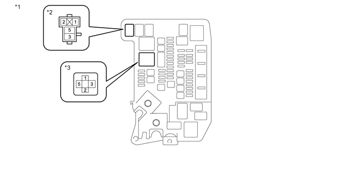
*1 Motor Compartment Relay Block *2 FC-IGCT Relay Holder *3 FC PWR Relay Holder - - Standard Resistance Tester Connection Condition Specified Condition 3 (FC-IGCT relay holder) - 1 (FC PWR relay holder) Always Below 1 Ω 3 (FC-IGCT relay holder) or 1 (FC PWR relay holder) - Body ground and other terminals Always 10 kΩ or higher -
Reinstall the FC PWR relay.
-
Reinstall the FC-IGCT relay.
Result Proceed to OK NG
OK
CHECK FOR INTERMITTENT PROBLEMS Click here
NG
REPAIR OR REPLACE HARNESS OR CONNECTOR
-