FC CONTROL SYSTEM, Diagnostic DTC:P1D92-450, P1D93-450
| DTC Code | DTC Name |
|---|---|
| P1D92-450 | FC Stack Air Pressure Sensor (FC Stack Inlet) Circuit Low |
| P1D93-450 | FC Stack Air Pressure Sensor (FC Stack Inlet) Circuit High |
DESCRIPTION
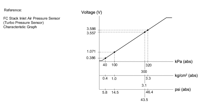
Air that flows into the FC stack is compressed by the FC air compressor with motor assembly, and then cooled down by the intercooler. The FC stack inlet air pressure sensor (turbo pressure sensor) monitors pressure of the air, and converts it into a voltage.
The FC stack inlet air pressure sensor (turbo pressure sensor) measures pressure of the air flowing into the FC stack as absolute pressure, thus, it can measure the FC stack inlet air pressure without influence from changes in the atmospheric pressure due to altitude, etc.
| DTC No. | Detection Item | DTC Detection Condition | Trouble Area | Warning Indicate |
|---|---|---|---|---|
| P1D92-450 | FC Stack Air Pressure Sensor (FC Stack Inlet) Circuit Low | If the FC air compressor speed is more than 1000 rpm and FC Stack Air Pressure Sensor (FC Stack Inlet) Voltage remains at less than 0.40 V for more than 3 seconds. This malfunction detection is actuated if the +B voltage is not low. (1 trip detection logic) |
|
Master Warning Light: Comes on |
| P1D93-450 | FC Stack Air Pressure Sensor (FC Stack Inlet) Circuit High | If the +B voltage is not low when the power switch is turned on (IG), FC Stack Air Pressure Sensor (FC Stack Inlet) Voltage remains at more than 4.65 V for more than 3 seconds. (1 trip detection logic) |
|
Master Warning Light: Comes on |
| Vehicle Condition | FC shutdown (power switch on (IG)) |
FC startup process | FC intermittent operation | FC is generating power (vehicle is in stationary) |
FC is generating power (vehicle is traveling) |
FC shutdown process |
|---|---|---|---|---|---|---|
| Data List "FC Mode" |
FC Shutdown | FC Startup Process | FC Working | FC Shutdown Process | ||
| Data List "FC Intermittent Operation" |
OFF | ON | OFF | OFF | ||
| DTC Detection | - | ○ | - | ○ | ○ | - |
| Vehicle Condition | FC shutdown (power switch on (IG)) |
FC startup process | FC intermittent operation | FC is generating power (vehicle is in stationary) |
FC is generating power (vehicle is traveling) |
FC shutdown process |
|---|---|---|---|---|---|---|
| Data List "FC Mode" |
FC Shutdown | FC Startup Process | FC Working | FC Shutdown Process | ||
| Data List "FC Intermittent Operation" |
OFF | ON | OFF | OFF | ||
| DTC Detection | ○ | ○ | ○ | ○ | ○ | - |
Tech Tips
By accessing the "FC Mode" and "FC Intermittent Operation" in the freeze frame data, the FC system condition at the time the malfunction occurred can be checked.
| DTC No. | Data List |
|---|---|
| P1D92-450 | FC Stack Air Pressure Sensor (FC Stack Inlet) Voltage |
| P1D93-450 |
The following items can be helpful when performing repairs:
-
Smoothed Value of FC Stack Air Pressure (FC Stack Inlet)
-
Air Compressor Revolution
-
FC Mode
Data List
Tech Tips
If DTCs are found, read the "FC Stack Air Pressure Sensor (FC Stack Inlet) Voltage" in the Data List on a GTS.
| FC Stack Air Pressure Sensor (FC Stack Inlet) Voltage | Malfunction |
|---|---|
| Less than 0.40 V |
|
| Higher than 4.65 V |
|
Tech Tips
It is suspected that malfunctions, or open/short circuits have occurred in the FC stack inlet air pressure sensor (turbo pressure sensor).
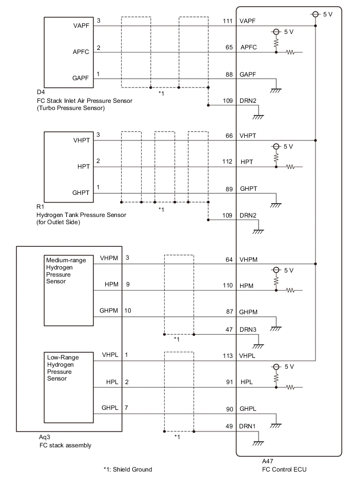
WIRING DIAGRAM
CAUTION / NOTICE / HINT
Note
When the vehicle is parked with the power switch off, if the FC control ECU judges that the FC stack temperature will go below 0°C (32°F), it activates the FC air compressor, hydrogen pump and FC cooling water pump for a maximum of 180 seconds and drains water from the FC stack assembly. When performing inspection or repairs with the power switch off (not on (IG) or on (READY)), disconnect the cable from the negative (-) auxiliary battery terminal before performing work (If the auxiliary battery voltage is needed to conduct inspection, warm up the FC system beforehand).
Tech Tips
After the repair, clear the DTCs and perform the following procedure to check that DTCs are not output.
-
Connect the GTS to the DLC3.
-
Turn the power switch on (READY) with the shift lever in P, and check the Data List that "FC Mode" is FC Working.
-
Enter the following menus: Powertrain / FC / Active Test / FC Air Compressor
-
Set the "FC Air Compressor" to 1500 rpm on the GTS, and then drive it for 5 seconds.
P01D92-450
-
Turn the power switch on (IG) and wait for 5 seconds or more.
P01D93-450
PROCEDURE
-
CHECK TERMINAL VOLTAGE (POWER SOURCE OF FC STACK INLET AIR PRESSURE SENSOR (TURBO PRESSURE SENSOR))
-
Disconnect the FC stack inlet air pressure sensor (turbo pressure sensor) connector.
-
Turn the power switch on (IG).
-
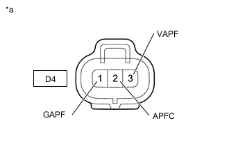
*a Front view of wire harness connector
(to FC stack inlet air pressure sensor (turbo pressure sensor))
Measure the voltage according to the value(s) in the table below.
Standard Voltage Tester Connection Condition Specified Condition D4-3 (VAPF) - D4-1 (GAPF) Power switch on (IG) 4.75 to 5.25 V D4-2 (APFC) - D4-1 (GAPF) Power switch on (IG) 4.935 to 5.065 V -
Turn the power switch off.
-
Reconnect the FC stack inlet air pressure sensor (turbo pressure sensor) connector.
Result Proceed to OK NG
NG 
CHECK HARNESS AND CONNECTOR (FC CONTROL ECU - FC STACK INLET AIR PRESSURE SENSOR (TURBO PRESSURE SENSOR)) Click here
OK 
-
-
REPLACE FC STACK INLET AIR PRESSURE SENSOR (TURBO PRESSURE SENSOR)
Result Proceed to NEXT
NEXT
-
CLEAR DTC
-
Connect the GTS to the DLC3.
-
Turn the power switch on (IG).
-
Turn the GTS on.
-
Enter the following menus: Powertrain / FC / Trouble Codes.
-
Clear the DTCs.
Powertrain > FC > Clear DTCs -
Turn the power switch off and wait for 3 minutes or more.
Result Result Proceed to P1D92-450 is output A P1D93-450 is output B
B
CHECK DTC OUTPUT Click here
A
-
-
CHECK DTC OUTPUT
-
Connect the GTS to the DLC3.
-
Turn the power switch on (IG).
-
Turn the GTS on.
-
Enter the following menus: Powertrain / FC / Data List / FC Mode
Powertrain > FC > Data ListTester Display FC Mode -
Turn the power switch on (READY) with the shift lever in P, and check the Data List that "FC Mode" is FC Working.
-
Enter the following menus: Powertrain / FC / Active Test / FC Air Compressor
Powertrain > FC > Active TestTester Display FC Air Compressor -
Set the "FC Air Compressor" to 1500 rpm on the GTS, and then drive it for 5 seconds.
-
Enter the following menus: Powertrain / FC / Trouble Codes.
-
Check for DTCs.
Powertrain > FC > Trouble CodesResult Result Proceed to DTC P1D92-450 is output A DTCs are not output B -
Turn the power switch off.
A 
REPLACE FC CONTROL ECU Click here
B
END
-
-
CHECK DTC OUTPUT
-
Connect the GTS to the DLC3.
-
Turn the power switch on (IG) and wait for 5 seconds or more.
-
Turn the GTS on.
-
Enter the following menus: Powertrain / FC / Trouble Codes.
-
Check for DTCs.
Powertrain > FC > Trouble CodesResult Result Proceed to DTC P1D93-450 is output A DTCs are not output B -
Turn the power switch off.
A
REPLACE FC CONTROL ECU Click here
B
END
-
-
CHECK HARNESS AND CONNECTOR (FC CONTROL ECU - FC STACK INLET AIR PRESSURE SENSOR (TURBO PRESSURE SENSOR))
-
Disconnect the FC control ECU connector.
-
Disconnect the FC stack inlet air pressure sensor (turbo pressure sensor) connector.
-
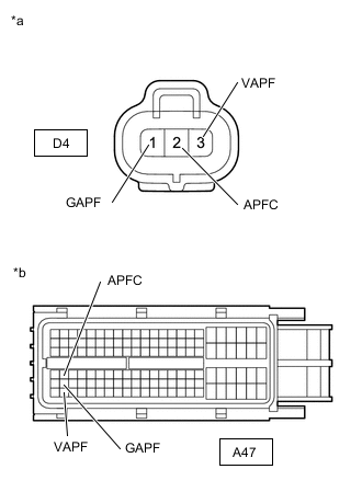
*a Front view of wire harness connector
(to FC Stack Inlet Air Pressure Sensor (Turbo Pressure Sensor))
*b Front view of wire harness connector
(to FC Control ECU)
Measure the resistance according to the value(s) in the table below.
Standard Resistance Tester Connection Condition Specified Condition A47-65 (APFC) - D4-2 (APFC) Always Below 1 Ω A47-88 (GAPF) - D4-1 (GAPF) Always Below 1 Ω A47-111 (VAPF) - D4-3 (VAPF) Always Below 1 Ω A47-65 (APFC) or D4-2 (APFC) - Body ground and other terminals Always 10 kΩ or higher A47-111 (VAPF) or D4-3 (VAPF) - Body ground and other terminals Always 10 kΩ or higher -
Reconnect the FC control ECU connector.
-
Reconnect the FC stack inlet air pressure sensor (turbo pressure sensor) connector.
Result Proceed to OK NG
OK
REPLACE FC CONTROL ECU Click here
NG
REPAIR OR REPLACE HARNESS OR CONNECTOR
-