FC CONTROL SYSTEM, Diagnostic DTC:P1D83-450
| DTC Code | DTC Name |
|---|---|
| P1D83-450 | Hydrogen Pump Inverter Performance |
DESCRIPTION
The FC control ECU regulates the FC water and hydrogen pump inverter assembly (hydrogen pump inverter) through use of communication signals, operating the hydrogen pump motor.
Based on the diagnostic information that can be obtained from the FC water and hydrogen pump inverter assembly (hydrogen pump inverter) through serial communication, the FC control ECU detects malfunctions in the hydrogen pump inverter or hydrogen pump.
| DTC No. | Detection Item | DTC Detection Condition | Trouble Area | Warning Indicate |
|---|---|---|---|---|
| P1D83-450 | Hydrogen Pump Inverter Performance | If the hydrogen pump inverter has stopped for more than 2 seconds with both of the following conditions met:
(1 trip detection logic) |
|
Master Warning Light: Comes on |
| Vehicle Condition | FC shutdown (power switch on (IG)) |
FC startup process | FC intermittent operation | FC is generating power (vehicle is in stationary) |
FC is generating power (vehicle is traveling) |
FC shutdown process |
|---|---|---|---|---|---|---|
| Data List "FC Mode" |
FC Shutdown | FC Startup Process | FC Working | FC Shutdown Process | ||
| Data List "FC Intermittent Operation" |
OFF | ON | OFF | OFF | ||
| DTC Detection | - | ○ | ○ | ○ | ○ | - |
Tech Tips
By accessing the "FC Mode" and "FC Intermittent Operation" in the freeze frame data, the FC system condition at the time the malfunction occurred can be checked.
| DTC No. | Data List |
|---|---|
| P1D83-450 |
|
The following items can be helpful when performing repairs:
-
Smoothed Value of Hydrogen Pump Motor Temperature
-
Hydrogen Pump Consumption Power
-
Hydrogen Pump Inverter Stop Malfunction
-
Hydrogen Pump Inverter Pause
-
Hydrogen Pump Inverter Output Limit
-
Hydrogen Pump Inverter Low Temperature Mode
Data List
-
Vehicle Speed
-
Shift Sensor Shift Position
-
Accelerator Degree
-
Ready
-
FC Mode
-
FC Intermittent Operation
-
FC Voltage before Boosting
-
FC Current
-
Target Low-range Hydrogen Pressure
-
Smoothed Value of Low-range Hydrogen Pressure
-
Target FC Stack Air Pressure (FC Stack Inlet)
-
Smoothed Value of FC Stack Air Pressure (FC Stack Inlet)
-
Target Mass Air Flow Value
-
Mass Air Flow Value
-
Target Air Compressor Revolution
-
Air Compressor Revolution
-
Target FC Stack Coolant Temperature (FC Stack Outlet)
-
Smoothed Value of FC Stack Coolant Temperature (FC Stack Outlet)
-
Exhaust Drainage Valve Driving Request
Common Data List items for FC inspection
| DTC No. | Active Test |
|---|---|
| P1D83-450 | Hydrogen Pump |
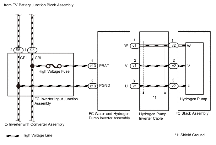
WIRING DIAGRAM
CAUTION / NOTICE / HINT
CAUTION:
-


Before the following operations are conducted, take precautions to prevent electric shock by turning the power switch off, wearing insulated gloves, and removing the service plug grips from both FC stack assembly and EV battery.
-
Inspecting the high-voltage system
-
Disconnecting the low voltage connector of the inverter with converter assembly
-
Disconnecting the low voltage connector of the EV battery
-
Disconnecting the low voltage connector of the FC stack assembly
-
Disconnecting the low voltage connector of the FC converter assembly
-
Tech Tips
No removal order is specified for the service plug grips of the FC stack assembly and EV battery.
-

After removing the service plug grip from the EV battery, put it in your pocket to prevent other technicians from accidentally reconnecting it while you are working on the high-voltage system. After removing the service grip from the FC stack assembly, store it in a safe location and use the "HIGH-VOLTAGE, DO NOT TOUCH" sign to notify other technicians that you are working on the high-voltage system.
-

*a Without waiting for 10 minutes After removal of the service plug grips of both FC stack assembly and EV battery, wait for at least 10 minutes before touching the high-voltage connectors and terminals. After waiting for 10 minutes, check the voltage at the terminals in the inspection point in the inverter with converter assembly. The voltage should be 0 V before beginning work.
Tech Tips
At least 10 minutes are necessary to discharge the high-voltage capacitors inside the inverter with converter assembly and FC stack assembly.
Note
-
When reinstalling the service plug grip to the FC stack assembly or the EV battery, slide the lever of the service plug until the letters "UNLOCK" are completely hidden, and insert it firmly.
-
When the vehicle is parked with the power switch off, if the FC control ECU judges that the FC stack temperature will go below 0°C (32°F), it activates the FC air compressor, hydrogen pump and FC cooling water pump for a maximum of 180 seconds and drains water from the FC stack assembly. When performing inspection or repairs with the power switch off (not on (IG) or on (READY)), disconnect the cable from the negative (-) auxiliary battery terminal before performing work (If the auxiliary battery voltage is needed to conduct inspection, warm up the FC system beforehand).
Tech Tips
-
Forcing the SOC of the EV battery to decrease by applying electrical loads such as turning on the air conditioning (HOT MAX, maximum airflow), or depressing the accelerator pedal with the shift lever in P, the "FC Intermittent Operation" of the Data List is easily to enter OFF (power generation mode).
After the repair, clear the DTCs and perform the following procedure to check that DTCs are not output.
-
Turn the power switch on (READY) with the shift lever in P, and check the Data List that "FC Mode" is FC Working and "FC Intermittent Operation" is OFF. Then, wait for at least 15 seconds or more.
PROCEDURE
-
CHECK DTC OUTPUT
Note
The freeze frame data is cleared when DTCs are cleared. Be sure to make a note of necessary data in advance.
-
Connect the GTS to the DLC3.
-
Turn the power switch on (IG).
-
Turn the GTS on.
-
Enter the following menus: Powertrain / FC / Trouble Codes.
-
Check for DTCs.
Powertrain > FC > Trouble CodesResult Result Proceed to No DTCs are output, or DTCs except the ones in the table below are also output. A Any of the following DTCs are also output. B Malfunction Content Relevant DTC Communication System Malfunction P1D84-450 Lost Communication with Hydrogen Pump Inverter P1DF2-450 Hydrogen Pump Inverter Drive Signal Stuck ON P1DF3-450 Hydrogen Pump Inverter Drive Signal Stuck OFF Tech Tips
DTC P1D83-450 may be set due to problems that cause the DTCs shown above to be output. If such happens, troubleshoot the suspected area(s) corresponding to the output DTC(s) in order starting with the listed DTCs shown in the table above.
-
Turn the power switch off.
B 
GO TO DTC CHART Click here
A 
-
-
CHECK DTC OUTPUT (EV)
Note
The freeze frame data is cleared when DTCs are cleared. Be sure to make a note of necessary data in advance.
-
Connect the GTS to the DLC3.
-
Turn the power switch on (IG).
-
Turn the GTS on.
-
Enter the following menus: Powertrain / EV / Trouble Codes.
-
Check for DTCs.
Powertrain > EV > Trouble CodesResult Result Proceed to No DTCs for the hybrid control system (EV) are output A DTCs for the hybrid control system (EV) are output B -
Turn the power switch off.
B
GO TO DTC CHART Click here
A
-
-
CHECK FREEZE FRAME DATA
-
Connect the GTS to the DLC3.
-
Turn the power switch on (IG).
-
Turn the GTS on.
-
Enter the following menus: Powertrain / FC / Trouble Codes.
-
Read the freeze frame data of DTC P1D83-450.
Confirmation Item Hydrogen Pump Inverter Abnormal Loading Hydrogen Pump Inverter Malfunction Hydrogen Pump Inverter Abnormal Input Result Result Proceed to The "Hydrogen Pump Inverter Abnormal Loading" of the freeze frame data shows ON. A The "Hydrogen Pump Inverter Malfunction" of the freeze frame data shows ON. B The "Hydrogen Pump Inverter Abnormal Input" of the freeze frame data shows ON. C All items of the freeze frame data shown above show OFF D -
Turn the power switch off.
B
REPLACE FC WATER AND HYDROGEN PUMP INVERTER ASSEMBLY (HYDROGEN PUMP INVERTER) Click here
C 
CHECK FC INVERTER INPUT JUNCTION ASSEMBLY Click here
D
REPLACE FC WATER AND HYDROGEN PUMP INVERTER ASSEMBLY (HYDROGEN PUMP INVERTER) Click here
A
-
-
CLEAR DTC
-
Connect the GTS to the DLC3.
-
Turn the power switch on (IG).
-
Turn the GTS on.
-
Enter the following menus: Powertrain / FC / Trouble Codes.
-
Clear the DTCs.
Powertrain > FC > Clear DTCs -
Turn the power switch off and wait for 3 minutes or more.
Result Proceed to NEXT
NEXT
-
-
PERFORM ACTIVE TEST USING GTS (HYDROGEN PUMP)
-
Connect the GTS to the DLC3.
-
Turn the power switch on (READY).
-
Turn the GTS on.
-
Enter the following menus: Powertrain / FC / Active Test / Hydrogen Pump
-
Select "Target Hydrogen Pump Revolution" and "Hydrogen Pump Revolution" in the Data List.
Powertrain > FC > Active TestActive Test Display Hydrogen Pump Data List Display Target Hydrogen Pump Revolution Hydrogen Pump Revolution -
Check the "Target Hydrogen Pump Revolution" and "Hydrogen Pump Revolution" of the Data List during an Active Test.
OK "Target Hydrogen Pump Revolution" and "Hydrogen Pump Revolution" change according to the Active Test values shown below. - Hydrogen Pump (Active Test) 1000 rpm 2000 rpm Target Hydrogen Pump Revolution
(Data List)
1000 rpm 2000 rpm Hydrogen Pump Revolution
(Data List)
800 to 1200 rpm 1800 to 2200 rpm Result Result Proceed to No change is found in the "Hydrogen Pump Revolution". A "Hydrogen Pump Revolution" changes, but the pump speed deviates from the "Target Hydrogen Pump Revolution" by 200 rpm or more. B Other than above. C -
Turn the power switch off.
B
REPLACE FC STACK ASSEMBLY Click here
C
CHECK FOR INTERMITTENT PROBLEMS Click here
A
-
-
CHECK HYDROGEN PUMP INVERTER CABLE
CAUTION:
Be sure to wear insulated gloves.
-
Check that the service plug grip is not installed to FC stack assembly and EV battery.
Note
After removing the service plug grip, do not turn the power switch on (READY), unless instructed by the repair manual because this may cause a malfunction.
-
Disconnect the v1 hydrogen pump inverter cable connector.
-
Disconnect the v2 hydrogen pump inverter cable connector.
-
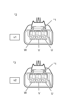
*1 Shield Ground *2 Hydrogen Pump Inverter Cable
(FC Water and Hydrogen Pump Inverter Assembly Side)
*3 Hydrogen Pump Inverter Cable
(FC Stack Assembly Side)
Using a megohmmeter set to 500 V, measure the insulation resistance according to the value(s) in the table below.
Note
Be sure to set the megohmmeter to 500 V when performing this test. Using a setting higher than 500 V can result in damage to the component being inspected.
Standard Resistance Tester Connection Condition Specified Condition v1-1 (W) - Body ground and shield ground Power switch off 10 MΩ or higher v1-2 (V) - Body ground and shield ground Power switch off 10 MΩ or higher v1-3 (U) - Body ground and shield ground Power switch off 10 MΩ or higher v2-1 (W) - Body ground and shield ground Power switch off 10 MΩ or higher v2-2 (V) - Body ground and shield ground Power switch off 10 MΩ or higher v2-3 (U) - Body ground and shield ground Power switch off 10 MΩ or higher Note
Wrap the terminals of three-phase AC cable with insulating tape to avoid them coming into contact with body ground.
-
Measure the resistance according to the value(s) in the table below.
Standard Resistance Tester Connection Condition Specified Condition v1-1 (W) - v2-1 (W) Power switch off Below 1 Ω v1-2 (V) - v2-2 (V) Power switch off Below 1 Ω v1-3 (U) - v2-3 (U) Power switch off Below 1 Ω v1-1 (W) - v2-3 (U) Power switch off 100 MΩ or higher v1-2 (V) - v2-1 (W) Power switch off 100 MΩ or higher v1-3 (U) - v2-2 (V) Power switch off 100 MΩ or higher -
Reconnect the v2 hydrogen pump inverter cable connector.
-
Reconnect the v1 hydrogen pump inverter cable connector.
Result Proceed to OK NG
NG
REPLACE HYDROGEN PUMP INVERTER CABLE
OK
-
-
REPLACE FC WATER AND HYDROGEN PUMP INVERTER ASSEMBLY (HYDROGEN PUMP INVERTER)
Result Proceed to NEXT
NEXT
-
CHECK DTC OUTPUT
-
Connect the GTS to the DLC3.
-
Turn the power switch on (IG).
-
Turn the GTS on.
-
Enter the following menus: Powertrain / FC / Data List / FC Mode, FC Intermittent Operation
Powertrain > FC > Data ListTester Display FC Mode FC Intermittent Operation -
Turn the power switch on (READY) with the shift lever in P, and check the Data List that "FC Mode" is FC Working and "FC Intermittent Operation" is OFF. Then, wait for at least 15 seconds or more.
-
Enter the following menus: Powertrain / FC / Trouble Codes.
-
Check for DTCs.
Powertrain > FC > Trouble CodesResult Result Proceed to DTC P1D83-450 is output* A DTCs are not output B
-
*: The hydrogen pump is malfunctioning
-
-
Turn the power switch off.
A
REPLACE FC STACK ASSEMBLY Click here
B
END
-
-
CHECK FC INVERTER INPUT JUNCTION ASSEMBLY
CAUTION:
Be sure to wear insulated gloves.
-
Check that the service plug grip is not installed to FC stack assembly and EV battery.
Note
After removing the service plug grip, do not turn the power switch on (READY), unless instructed by the repair manual because this may cause a malfunction.
-
Remove the FC inverter input junction assembly.
Note
Do not allow foreign matter or water droplets to enter the FC inverter input junction assembly.
-
Measure the resistance according to the value(s) in the table below.
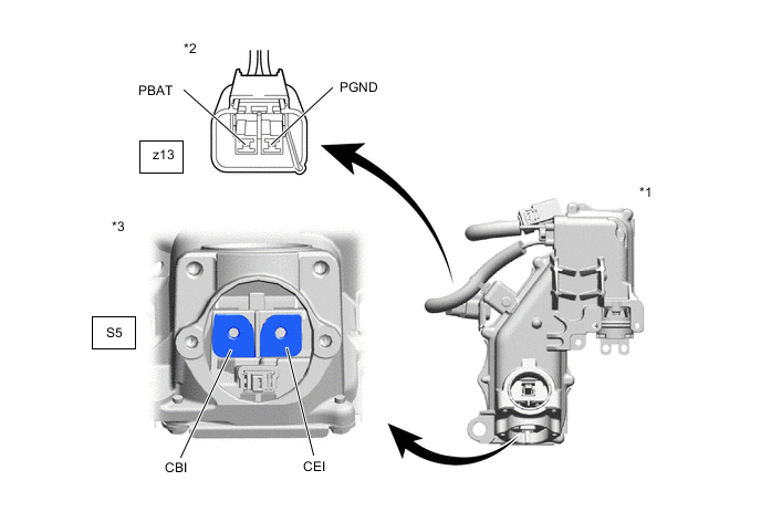
*1 FC Inverter Input Junction Assembly *2 FC Inverter Input Junction Assembly
(FC Water and Hydrogen Pump Inverter Assembly Side)
*3 FC Inverter Input Junction Assembly
(Frame Wire Side)
- - Standard Resistance Tester Connection Condition Specified Condition z13-1 (PBAT) - S5-1 (CBI) Power switch off Below 1 Ω z13-2 (PGND) - S5-2 (CEI) Power switch off Below 1 Ω -
Install the FC inverter input junction assembly.
Result Proceed to OK NG
OK
REPLACE FC WATER AND HYDROGEN PUMP INVERTER ASSEMBLY (HYDROGEN PUMP INVERTER) Click here
NG
-
-
CHECK HIGH VOLTAGE FUSE
CAUTION:
Be sure to wear insulated gloves.
-
Check that the service plug grip is not installed to FC stack assembly and EV battery.
Note
After removing the service plug grip, do not turn the power switch on (READY), unless instructed by the repair manual because this may cause a malfunction.
-
Remove the FC inverter input junction assembly.
Note
Do not allow foreign matter or water droplets to enter the FC inverter input junction assembly.
-
Remove the junction block service cover from the FC inverter input junction assembly.
-
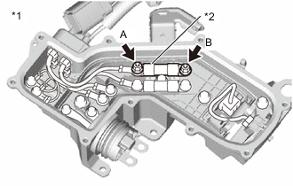
*1 FC Inverter Input Junction Assembly *2 High Voltage Fuse Check that bolts A and B have been tightened securely.
-
Measure the resistance according to the value(s) in the table below.
Standard Resistance Tester Connection Condition Specified Condition A - B Power switch off Below 1 Ω Result Proceed to OK NG
OK
REPLACE FC INVERTER INPUT JUNCTION ASSEMBLY Click here
NG
REPLACE HIGH VOLTAGE FUSE Click here
-