FC CONTROL SYSTEM, Diagnostic DTC:P1D3F-450
| DTC Code | DTC Name |
|---|---|
| P1D3F-450 | FC Stack Voltage Low |
DESCRIPTION
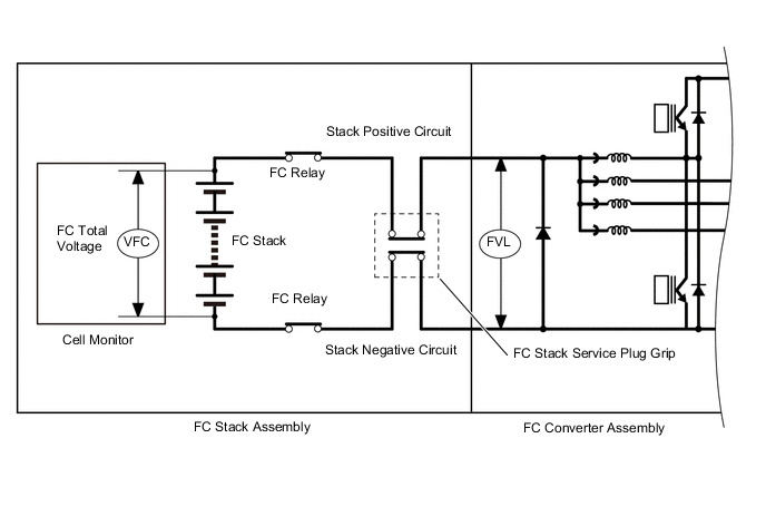
During FC power generation, the FC stack generates a voltage of 220 to 370 V and feeds it into the FC converter assembly through the stack positive and negative circuits. (The stack voltage gradually decreases as the FC system stops)
If a voltage, which is normally 220 to 370 V, between the stack positive and negative circuits decreases abnormally, due to overcurrent caused by short-circuited terminals, the FC control ECU interprets it as a malfunction and store this DTC.
| DTC No. | Detection Item | DTC Detection Condition | Trouble Area | Warning Indicate |
|---|---|---|---|---|
| P1D3F-450 | FC Stack Voltage Low | If the FC stack total voltage (sum of each cell voltage measured by the cell monitor) has decreased below a specified voltage. This malfunction detection is activated when the amount of supplied air and hydrogen is sufficient during power generation of the FC stack ("FC Mode" is in FC Working). (1 trip detection logic) |
FC stack assembly | Master Warning Light: Comes on |
Tech Tips
If there is a short circuit in the FC stack output (trigger for this DTC), the FC system cannot be actuated. If actuation is allowed, the malfunction has not been reproduced.
| Vehicle Condition | FC shutdown (power switch on (IG)) |
FC startup process | FC intermittent operation | FC is generating power (vehicle is in stationary) |
FC is generating power (vehicle is traveling) |
FC shutdown process |
|---|---|---|---|---|---|---|
| Data List "FC Mode" |
FC Shutdown | FC Startup Process | FC Working | FC Shutdown Process | ||
| Data List "FC Intermittent Operation" |
OFF | ON | OFF | OFF | ||
| DTC Detection | - | - | ○ | ○ | ○ | - |
Tech Tips
By accessing the "FC Mode" and "FC Intermittent Operation" in the freeze frame data, the FC system condition at the time the malfunction occurred can be checked.
| DTC No. | Data List |
|---|---|
| P1D3F-450 |
|
The following items can be helpful when performing repairs:
-
Vehicle Speed
-
Shift Sensor Shift Position
-
Accelerator Degree
-
Ready
-
FC Mode
-
FC Intermittent Operation
-
FC Current
-
Target Low-range Hydrogen Pressure
-
Smoothed Value of Low-range Hydrogen Pressure
-
Target Hydrogen Pump Revolution
-
Hydrogen Pump Revolution
-
Target FC Stack Air Pressure (FC Stack Inlet)
-
Smoothed Value of FC Stack Air Pressure (FC Stack Inlet)
-
Target Mass Air Flow Value
-
Mass Air Flow Value
-
Target Air Compressor Revolution
-
Air Compressor Revolution
-
Target FC Stack Coolant Temperature (FC Stack Outlet)
-
Smoothed Value of FC Stack Coolant Temperature (FC Stack Outlet)
Common Data List items for FC inspection
CAUTION / NOTICE / HINT
Note
When the vehicle is parked with the power switch off, if the FC control ECU judges that the FC stack temperature will go below 0°C (32°F), it activates the FC air compressor, hydrogen pump and FC cooling water pump for a maximum of 180 seconds and drains water from the FC stack assembly. When performing inspection or repairs with the power switch off (not on (IG) or on (READY)), disconnect the cable from the negative (-) auxiliary battery terminal before performing work (If the auxiliary battery voltage is needed to conduct inspection, warm up the FC system beforehand).
Tech Tips
-
Forcing the SOC of the EV battery to decrease by applying electrical loads such as turning on the air conditioning (HOT MAX, maximum airflow), or depressing the accelerator pedal with the shift lever in P, the "FC Intermittent Operation" of the Data List is easily to enter OFF (power generation mode).
After the repair, clear the DTCs and perform the following procedure to check that DTCs are not output.
-
Turn the power switch on (READY) with the shift lever in P, and check the Data List that "FC Mode" is FC Working and "FC Intermittent Operation" is OFF.
-
Check that the "FC Total Voltage" value of the Data List is more than 200 V (except for a situation where an ambient temperature is below 0°C (32°F) or intermittent operation is active).
PROCEDURE
-
CHECK DTC OUTPUT
Note
The freeze frame data is cleared when DTCs are cleared. Be sure to make a note of necessary data in advance.
-
Connect the GTS to the DLC3.
-
Turn the power switch on (IG).
-
Turn the GTS on.
-
Enter the following menus: Powertrain / FC / Trouble Codes.
-
Check for DTCs.
Powertrain > FC > Trouble CodesResult Result Proceed to P1D3F-450 only is output, or DTCs except the ones in the table below are also output. A Any of the following DTCs are also output. B Malfunction Content Relevant DTC Microcomputer Malfunction / Power Source Circuit Malfunction P1DCF-450 Cell Monitor Performance Communication System Malfunction P1D5F-450 Lost Communication with Cell Monitor Sensor and Actuator Circuit Malfunction P1D24-450 Hydrogen Pump Speed Control Performance P1D7F-450 Air Compressor Speed Control Performance P1E36-450 Tank Shut Valve 1 Stuck Open or Close P1E38-450 Tank Shut Valve 2 Stuck Open or Close P1E48-450 Barometric Pressure Sensor / FC Stack Air Pressure Sensor (FC Stack Inlet)Correlation System Malfunction P0101-450 Mass Air Flow Circuit Range/Performance P1D91-450 Air Control System Performance P1DC0-450 Low-range Hydrogen Pressure Too Low P1DC5-450 Air Pressure Too High P1E42-450 Hydrogen Pressure Leak (Excessive Hydrogen Flow) Tech Tips
DTC P1D3F-450 may be set due to problems that cause the DTCs shown above to output. If such happens, troubleshoot the suspected area(s) corresponding to the output DTC(s) in order of the listed DTCs shown in the table above.
-
Turn the power switch off.
B 
GO TO DTC CHART Click here
A 
-
-
CLEAR DTC
-
Connect the GTS to the DLC3.
-
Turn the power switch on (IG).
-
Turn the GTS on.
-
Enter the following menus: Powertrain / FC / Trouble Codes.
-
Clear the DTCs.
Powertrain > FC > Clear DTCs -
Turn the power switch off and wait for 3 minutes or more.
Result Proceed to NEXT
NEXT
-
-
CHECK FREEZE FRAME DATA
Note
The freeze frame data is cleared when DTCs are cleared. Be sure to make a note of necessary data in advance.
-
Connect the GTS to the DLC3.
-
Turn the power switch on (IG).
-
Turn the GTS on.
-
Enter the following menus: Powertrain / FC / Trouble Codes.
-
Read the freeze frame data of DTC P1D3F-450.
Result Result Proceed to Other than below A Voltage difference between "FC Total Voltage" and "FC Voltage before Boosting" is more than 50 V* B
-
*: The cell monitor is malfunctioning
-
-
Turn the power switch off.
B
REPLACE FC STACK ASSEMBLY Click here
A
-
-
READ VALUE USING GTS (FC MODE, FC INTERMITTENT OPERATION, FC TOTAL VOLTAGE)
-
Connect the GTS to the DLC3.
-
Turn the power switch on (IG).
-
Turn the GTS on.
-
Enter the following menus: Powertrain / FC / Data List / FC Mode, FC Intermittent Operation, FC Total Voltage
Powertrain > FC > Data ListTester Display FC Mode FC Intermittent Operation FC Total Voltage -
Turn the power switch on (READY) with the shift lever in P, and check the Data List that "FC Mode" is FC Working and "FC Intermittent Operation" is OFF.
-
Read the "FC Total Voltage" of the Data List.
Result Result Proceed to FC system can be actuated A FC system cannot be actuated, and "FC Total Voltage" is less than 200 V B
B
REPLACE FC STACK ASSEMBLY Click here
A
-
-
SIMULATION TEST
-
Connect the GTS to the DLC3.
-
Turn the power switch on (IG).
-
Turn the GTS on.
-
Drive the vehicle for 10 minutes according to the freeze frame data (Vehicle Speed, Accelerator Degree, etc.)
CAUTION:
Perform this road test only in an appropriate safe location, in accordance with all local laws.
Tech Tips
If vehicle speeds, accelerator pedal positions, road conditions, ambient temperatures and climates at the time the malfunction occurred can be found out, take them into account.
-
Enter the following menus: Powertrain / FC / Trouble Codes.
-
Check for DTCs.
Powertrain > FC > Trouble CodesResult Result Proceed to DTCs are not output A DTC P1D3F-450 is output B -
Turn the power switch off.
A
CHECK FOR INTERMITTENT PROBLEMS Click here
B
REPLACE FC STACK ASSEMBLY Click here
-