FC CONTROL SYSTEM, Diagnostic DTC:P1D27-450, P1D28-450
| DTC Code | DTC Name |
|---|---|
| P1D27-450 | FC Stack Coolant Temperature Sensor (Radiator Outlet) Circuit Low |
| P1D28-450 | FC Stack Coolant Temperature Sensor (Radiator Outlet) Circuit High |
DESCRIPTION
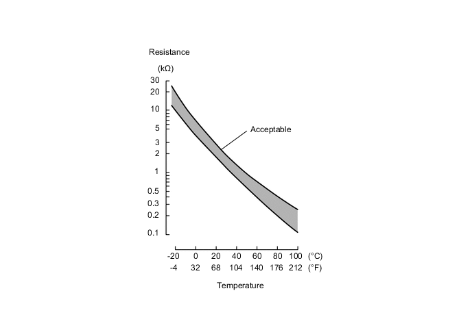
The water temperature sensor (for radiator outlet side) has a built-in thermistor with a resistance that varies according to the temperature of the FC coolant. When the FC coolant temperature is low, the resistance of the thermistor increases. When the temperature is high, the resistance drops. These variations in resistance are transmitted to the FC control ECU as voltage changes.
The water temperature sensor (for radiator outlet side) is connected to the FC control ECU, and a power voltage of 5 V is supplied from the WTR terminal of the FC control ECU to the sensor via resistor R. Since resistor R and the sensor are connected in series, resistance varies as an FC stack coolant temperature changes, and potential of the WTR terminal also varies.
| DTC No. | Detection Item | DTC Detection Condition | Trouble Area | Warning Indicate |
|---|---|---|---|---|
| P1D27-450 | FC Stack Coolant Temperature Sensor (Radiator Outlet) Circuit Low | If the +B voltage is not low when the power switch is turned on (IG), FC Stack Coolant Temperature Sensor (Radiator Outlet) Voltage remains at less than 0.1 V for more than 3 seconds. (1 trip detection logic) |
|
Master Warning Light: Comes on |
| P1D28-450 | FC Stack Coolant Temperature Sensor (Radiator Outlet) Circuit High | If the +B voltage is not low when the power switch is turned on (IG), FC Stack Coolant Temperature Sensor (Radiator Outlet) Voltage remains at more than 4.9 V for more than 3 seconds. (1 trip detection logic) |
|
Master Warning Light: Comes on |
| Vehicle Condition | FC shutdown (power switch on (IG)) |
FC startup process | FC intermittent operation | FC is generating power (vehicle is in stationary) |
FC is generating power (vehicle is traveling) |
FC shutdown process |
|---|---|---|---|---|---|---|
| Data List "FC Mode" |
FC Shutdown | FC Startup Process | FC Working | FC Shutdown Process | ||
| Data List "FC Intermittent Operation" |
OFF | ON | OFF | OFF | ||
| DTC Detection | ○ | ○ | ○ | ○ | ○ | - |
| DTC No. | Data List |
|---|---|
| P1D27-450 |
|
| P1D28-450 |
WIRING DIAGRAM
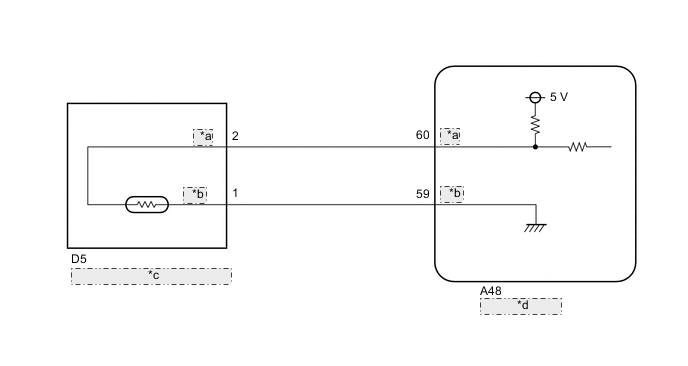
| *a | WTR |
| *b | GWTR |
| *c | Water Temperature Sensor (for Radiator Outlet Side) |
| *d | FC Control ECU |
CAUTION / NOTICE / HINT
Note
When the vehicle is parked with the power switch off, if the FC control ECU judges that the FC stack temperature will go below 0°C (32°F), it activates the FC air compressor, hydrogen pump and FC cooling water pump for a maximum of 180 seconds and drains water from the FC stack assembly. When performing inspection or repairs with the power switch off (not on (IG) or on (READY)), disconnect the cable from the negative (-) auxiliary battery terminal before performing work (If the auxiliary battery voltage is needed to conduct inspection, warm up the FC system beforehand).
Tech Tips
After the repair, clear the DTCs and perform the following procedure to check that DTCs are not output.
-
Turn the power switch on (IG) and wait for 3 seconds or more.
PROCEDURE
-
READ VALUE USING GTS (FC STACK COOLANT TEMPERATURE SENSOR (RADIATOR OUTLET) VOLTAGE)
-
Connect the GTS to the DLC3.
-
Turn the power switch on (IG).
-
Turn the GTS on.
-
Enter the following menus: Powertrain / FC / Data List / FC Stack Coolant Temperature Sensor (Radiator Outlet) Voltage
Powertrain > FC > Data ListTester Display FC Stack Coolant Temperature Sensor (Radiator Outlet) Voltage -
Read the value displayed on the GTS.
Result FC Stack Coolant Temperature Sensor (Radiator Outlet) Voltage Proceed to Higher than 4.9 V A Less than 0.1 V B Tech Tips
-
If there is an open circuit, the GTS indicates higher than 4.9 V.
-
If there is a short circuit, the GTS indicates less than 0.1 V.
-
B 
READ VALUE USING GTS (CHECK FOR SHORT IN WIRE HARNESS) Click here
A 
-
-
READ VALUE USING GTS (CHECK FOR OPEN IN WIRE HARNESS)
-
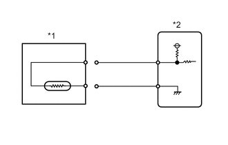
Disconnect the water temperature sensor (for radiator outlet side) connector.
-
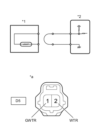
*1 Water Temperature Sensor (for Radiator Outlet Side) *2 FC Control ECU *a Front view of wire harness connector
(to Water Temperature Sensor (for Radiator Outlet Side))
Connect terminals 2 (WTR) and 1 (GWTR) of the water temperature sensor (for radiator outlet side) connector on the wire harness side.
-
Connect the GTS to the DLC3.
-
Turn the power switch on (IG).
-
Turn the GTS on.
-
Enter the following menus: Powertrain / FC / Data List / FC Stack Coolant Temperature Sensor (Radiator Outlet) Voltage
Powertrain > FC > Data ListTester Display FC Stack Coolant Temperature Sensor (Radiator Outlet) Voltage -
Read the value displayed on the GTS.
Standard value Less than 0.1 V (Short circuit) -
Turn the power switch off.
-
Reconnect the water temperature sensor (for radiator outlet side) connector.
Result Proceed to OK NG
OK 
REPLACE WATER TEMPERATURE SENSOR (FOR RADIATOR OUTLET SIDE) Click here
NG
-
-
CHECK HARNESS AND CONNECTOR (FC CONTROL ECU - WATER TEMPERATURE SENSOR (FOR RADIATOR OUTLET SIDE))
-
Disconnect the FC control ECU connector.
-
Disconnect the water temperature sensor (for radiator outlet side) connector.
-
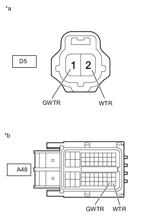
*a Front view of wire harness connector
(to Water Temperature Sensor (for Radiator Outlet Side))
*b Front view of wire harness connector
(to FC Control ECU)
Measure the resistance according to the value(s) in the table below.
Standard Resistance Tester Connection Condition Specified Condition A48-60 (WTR) - D5-2 (WTR) Always Below 1 Ω A48-59 (GWTR) - D5-1 (GWTR) Always Below 1 Ω -
Reconnect the water temperature sensor (for radiator outlet side) connector.
-
Reconnect the FC control ECU connector.
Result Proceed to OK NG
OK
REPLACE FC CONTROL ECU Click here
NG
REPAIR OR REPLACE HARNESS OR CONNECTOR
-
-
READ VALUE USING GTS (CHECK FOR SHORT IN WIRE HARNESS)
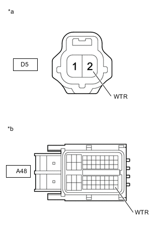
-
Disconnect the D5 water temperature sensor (for radiator outlet side) connector.
-
Connect the GTS to the DLC3.
-
Turn the power switch on (IG).
-
Turn the GTS on.
-
*1 Water Temperature Sensor (for Radiator Outlet Side) *2 FC Control ECU Enter the following menus: Powertrain / FC / Data List / FC Stack Coolant Temperature Sensor (Radiator Outlet) Voltage
Powertrain > FC > Data ListTester Display FC Stack Coolant Temperature Sensor (Radiator Outlet) Voltage -
Read the value displayed on the GTS.
Standard value Higher than 4.9 V (Open circuit) -
Turn the power switch off.
-
Reconnect the water temperature sensor (for radiator outlet side) connector.
Result Proceed to OK NG
OK
REPLACE WATER TEMPERATURE SENSOR (FOR RADIATOR OUTLET SIDE) Click here
NG
-
-
CHECK HARNESS AND CONNECTOR (FC CONTROL ECU - WATER TEMPERATURE SENSOR (FOR RADIATOR OUTLET SIDE))
-
Disconnect the FC control ECU connector.
-
Disconnect the water temperature sensor (for radiator outlet side) connector.
-
*a Front view of wire harness connector
(to Water Temperature Sensor (for Radiator Outlet Side))
*b Front view of wire harness connector
(to FC Control ECU)
Measure the resistance according to the value(s) in the table below.
Standard Resistance Tester Connection Condition Specified Condition A48-60 (WTR) or D5-2 (WTR) - Body ground and other terminals Always 10 kΩ or higher -
Reconnect the water temperature sensor (for radiator outlet side) connector.
-
Reconnect the FC control ECU connector.
Result Proceed to OK NG
OK
REPLACE FC CONTROL ECU Click here
NG
REPAIR OR REPLACE HARNESS OR CONNECTOR
-