FC CONTROL SYSTEM, Diagnostic DTC:P0101-450
| DTC Code | DTC Name |
|---|---|
| P0101-450 | Mass Air Flow Circuit Range/Performance |
DESCRIPTION
The air system of the FC system feeds the FC stack with oxygen, so that the FC stack can generate power. The mass air flow meter is used to measure the airflow rate from the FC air compressor to the FC stack, contributing to appropriate airflow control for the FC stack power generation.
If a measured airflow rate of the mass air flow meter has abnormally deviated from the predicted airflow rate that is obtained from the FC air compressor speed, the FC control ECU interprets it as sensor range deviation, and sets the DTC.
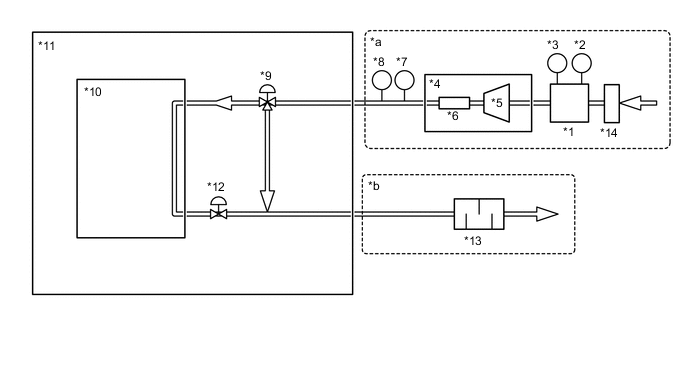
| *1 | Mass Air Flow Meter | *2 | Intake Air Temperature Sensor |
| *3 | Airflow sensor | *4 | FC Air Compressor with Motor Assembly |
| *5 | FC Air Compressor | *6 | Intercooler |
| *7 | FC Gas Temperature Sensor | *8 | FC Stack Inlet Air Pressure Sensor (Turbo Pressure Sensor) |
| *9 | Air Shunt Valve | *10 | FC Stack |
| *11 | FC Stack Assembly | *12 | Air Pressure Regulating Valve |
| *13 | FC Exhaust Tail Pipe Assembly | *14 | Air Cleaner Filter Element Sub-assembly |
| *a | Air intake system | *b | Air exhaust system |
| DTC No. | Detection Item | DTC Detection Condition | Trouble Area | Warning Indicate |
|---|---|---|---|---|
| P0101-450 | Mass Air Flow Circuit Range/Performance | If the following 2 values have significantly exceeded the thresholds, the DTC will be set:
This malfunction detection begins when "FC Mode" is in the conditions other than FC Shutdown. (1 trip detection logic) |
|
Master Warning Light: Comes on |
Tech Tips
This DTC will be set if the correlation between air compressor speeds, air pressure and mass air flow sensor airflow rates has deviated due to clogged or damaged FC air system lines or a malfunctioning mass air flow meter.
| Vehicle Condition | FC shutdown (power switch on (IG)) |
FC startup process | FC intermittent operation | FC is generating power (vehicle is in stationary) |
FC is generating power (vehicle is traveling) |
FC shutdown process |
|---|---|---|---|---|---|---|
| Data List "FC Mode" |
FC Shutdown | FC Startup Process | FC Working | FC Shutdown Process | ||
| Data List "FC Intermittent Operation" |
OFF | ON | OFF | OFF | ||
| DTC Detection | - | ○ | ○ | ○ | ○ | ○ |
Tech Tips
By accessing the "FC Mode" in the freeze frame data, the FC system condition at the time the malfunction occurred can be checked.
| DTC No. | Data List |
|---|---|
| P0101-450 |
|
The following items can be helpful when performing repairs:
-
Vehicle Speed
-
Shift Sensor Shift Position
-
Accelerator Degree
-
Ready
-
FC Mode
-
FC Intermittent Operation
-
FC Voltage before Boosting
-
FC Current
-
Target Low-range Hydrogen Pressure
-
Smoothed Value of Low-range Hydrogen Pressure
-
Target FC Stack Air Pressure (FC Stack Inlet)
-
Target Mass Air Flow Value
-
Target Air Compressor Revolution
-
Target FC Stack Coolant Temperature (FC Stack Outlet)
-
Smoothed Value of FC Stack Coolant Temperature (FC Stack Outlet)
Common Data List items for FC inspection
| DTC No. | Active Test |
|---|---|
| P0101-450 | FC Air Compressor |
| DTC No. | Utility |
|---|---|
| P0101-450 | Check Mode (Air System Component Inspection) |
Tech Tips
By entering "Check Mode", abnormalities in the air shunt valve, air pressure regulating valve or air system lines can be found.
CAUTION / NOTICE / HINT
Note
When the vehicle is parked with the power switch off, if the FC control ECU judges that the FC stack temperature will go below 0°C (32°F), it activates the FC air compressor, hydrogen pump and FC cooling water pump for a maximum of 180 seconds and drains water from the FC stack assembly. When performing inspection or repairs with the power switch off (not on (IG) or on (READY)), disconnect the cable from the negative (-) auxiliary battery terminal before performing work (If the auxiliary battery voltage is needed to conduct inspection, warm up the FC system beforehand).
Tech Tips
After the repair, clear the DTCs and perform the following procedure to check that DTCs are not output.
-
Drive the vehicle for 10 minutes according to the freeze frame data (Vehicle Speed, Accelerator Degree, Mass Air Flow Value).
CAUTION:
Perform this road test only in an appropriate safe location, in accordance with all local laws.
PROCEDURE
-
CHECK DTC OUTPUT
Note
The freeze frame data is cleared when DTCs are cleared. Be sure to make a note of necessary data in advance.
-
Connect the GTS to the DLC3.
-
Turn the power switch on (IG).
-
Turn the GTS on.
-
Enter the following menus: Powertrain / FC / Trouble Codes.
-
Check for DTCs.
Powertrain > FC > Trouble CodesResult Result Proceed to P0101-450 only is output, or DTCs except the ones in the table below are also output. A Any of the following DTCs are also output. B Malfunction Content Relevant DTC System Malfunction P1D7F-450 Air Compressor Speed Control Performance P1E48-450 Barometric Pressure Sensor / FC Stack Air Pressure Sensor (FC Stack Inlet)Correlation Tech Tips
DTC P0101-450 may be set due to problems that cause the DTCs shown above to be output. If such happens, troubleshoot the suspected area(s) corresponding to the output DTC(s) in order starting with the listed DTCs shown in the table above.
-
Turn the power switch off.
B 
GO TO DTC CHART Click here
A 
-
-
CHECK DTC OUTPUT (EV)
Note
The freeze frame data is cleared when DTCs are cleared. Be sure to make a note of necessary data in advance.
-
Connect the GTS to the DLC3.
-
Turn the power switch on (IG).
-
Turn the GTS on.
-
Enter the following menus: Powertrain / EV / Trouble Codes.
-
Check for DTCs.
Powertrain > EV > Trouble CodesResult Result Proceed to DTCs other than those shown in the table below are output A Any of the DTCs shown in the table below are output. B Malfunction Content Relevant DTC Microcomputer Malfunction P1D8F-474, 475, 476, 477, 478, 479, 481, 482, 483, 484 FC Air Compressor Motor "A" Control Module Sensor and Actuator Circuit Malfunction P1D75-450 FC Air Compressor Motor "A" Position Sensor Circuit P1D76-450 FC Air Compressor Motor "A" Position Sensor Circuit Range/Performance P1D77-450 FC Air Compressor Motor "A" Position Sensor Circuit Low Tech Tips
DTC P0101-450 may be set due to problems that cause the DTCs shown above to output. If such happens, troubleshoot the suspected area(s) corresponding to the output DTC(s) in order of the listed DTCs shown in the table above.
-
Turn the power switch off.
B
GO TO DTC CHART (HYBRID CONTROL SYSTEM) Click here
A
-
-
CLEAR DTC
-
Connect the GTS to the DLC3.
-
Turn the power switch on (IG).
-
Turn the GTS on.
-
Enter the following menus: Powertrain / FC / Trouble Codes.
-
Clear the DTCs.
Powertrain > FC > Clear DTCs -
Turn the power switch off and wait for 3 minutes or more.
Result Proceed to NEXT
NEXT
-
-
CHECK AIR CLEANER FILTER ELEMENT SUB-ASSEMBLY
-
Check that the air cleaner filter element sub-assembly is not clogged.
OK The air cleaner filter element sub-assembly is not clogged Result Proceed to OK NG
OK 
GO TO STEP 6 Click here
NG
-
-
CLEAN OR REPLACE AIR CLEANER FILTER ELEMENT SUB-ASSEMBLY
-
Clean or replace the air cleaner filter element sub-assembly.
Result Proceed to NEXT
NEXT
-
-
CHECK INTAKE AND EXHAUST PIPING
-
Check that no air comes in without flowing through each part of the intake air system and the exhaust drainage pipe is not clogged, disconnected, or damaged.
OK The intake and exhaust piping is not clogged, disconnected or damaged Result Proceed to OK NG
OK
REPLACE MASS AIR FLOW METER Click here
NG
REPAIR OR REPLACE MALFUNCTIONING PARTS
-