FC CONTROL SYSTEM DATA LIST / ACTIVE TEST
-
DATA LIST
Note
-
Some Data List values may vary significantly if there are slight differences in the vehicle condition. Variations may also occur due to aging of the vehicle. Due to these considerations, it is not always possible to provide definite values to be used for judgment of malfunctions. It is possible that a malfunction may be present even if measured values are within the reference range.
-
In the event of a problem with intricate symptoms, collect sample data from another vehicle of the same model operating under same conditions in order to reach an overall judgment by comparing all the items in the Data List.
-
Connect the GTS to the DLC3.
-
Turn the power switch on (IG).
-
Turn the GTS on.
-
Enter the following menus: Powertrain / FC / Data List.
-
Check the results by referring to the following table.
Tech Tips
-
When reviewing Data List information, try to select only the specific Data List items related to the inspection being performed. If all items are selected when checking the Data List, the interval between updates for each item will be longer, resulting in delayed.
-
Using a custom list makes it possible to easily select smaller groups of related Data List items.
-
The following custom lists are available:
-
All Data
-
Primary
-
Air System
-
Cooling System
-
Hydrogen Filling
-
FC Stack/Cell Monitor
-
Hydrogen Pump
-
Tank Shut Valve
-
Insulation Abnormal
-
Powertrain > FC > Data ListTester Display Measurement Item Range Normal Condition Diagnostic Note Battery Voltage Auxiliary battery voltage - 11.00 to 14.70 V:
Power switch on (IG)
+B terminal Fuel Lid Interlock Switch Fuel lid interlock switch condition ON or OFF ON:
Fuel lid open
OFF:
Fuel lid fully closed
-
The interlock switch is used to prevent the vehicle from running while the hydrogen filling nozzle is connected to the vehicle. Thus, the interlock switch monitors if the fuel lid is open or closed.
-
The hydrogen fuel control ECU assembly determines whether the fuel lid is open or closed through interlock switch signals from both fuel filler opening lid sub-assembly (hinge switch) and fuel filler opening lid switch sub-assembly.
Fuel Lid Open Switch Fuel lid opener switch ON or OFF ON:
Fuel lid opener switch pressed
- Total Distance Traveled Drive total distance Min.: 0 km (0 mile), Max.: 16777215 km (10425361 mile) - - Cell Monitor Sleep Mode Sleep request signals to the cell monitor ON or OFF OFF:
Power switch on (READY)
Even if the FC control ECU transmits a sleep request to the cell monitor, sleep mode may not be activated due to the FC stack power generation state. EV System Wakeup Signal Wakeup request signals to the EV control ECU ON or OFF - - FC Related Parts Drive Voltage Power supply voltage applied from the FC PWR relay Min.: 0 V, Max.: 79.99 V 11.00 to 14.70 V:
Power switch on (IG)
This is the power supply voltage that is used to actuate the following valves:
Air shunt valve, Air pressure regulating valve, exhaust drainage valve, FC cooling water temperature control valve.
FC Voltage before Boosting Measured power generation voltage of the FC stack - 0 V:
Power switch on (IG)
0 to 370.0 V:
Vehicle stationary with power switch on (READY) ("FC Mode" in the Data List shows FC Working, and "FC Intermittent Operation" shows OFF)
- FC Current Measured power generation current of the FC stack - 0 to 50.00 A:
Vehicle stationary with power switch on (READY) ("FC Mode" in the Data List shows FC Working), A/C off, Electrical load off
- FC Mode Mode of the FC stack operation FC Shutdown / FC Shutdown Process / FC Startup Process / FC Working FC Shutdown:
Power switch on (IG)
FC Shutdown
-
FC stack has stopped operating
-
The vehicle is in READY OFF mode, or FC Shutdown is completed
FC Startup Process
-
The components and pipes employed by the hydrogen supply system (where high-range and mid-range pressures are applied) and the hydrogen circulation system (where low-range pressures are applied), which are located after the tank shut valve, are pressurized by supplying compressed hydrogen gas from the hydrogen tank assembly. During pressurization, high-range and low-range hydrogen pressures are monitored.
FC Working
-
FC stack is ready to generate power.
FC Shutdown Process
-
The components and pipes employed by the hydrogen supply system (where high-range and mid-range pressures are applied) and the hydrogen circulation system (where low-range pressures are applied) is depressurized. During depressurization, the high-range and mid-range pressures in the hydrogen supply system are monitored.
FC Intermittent Operation FC stack power generation waiting state (including very small power generation) ON or OFF ON:
FC intermittent operation
-
During intermittent operation, low-range hydrogen pressures in the hydrogen circulation system (low-pressure system) located after the hydrogen injectors is monitored.
-
Even when the FC Intermittent Operation is ON, very small power may be generated.
FC Stack Coolant Electrically Conductive Reforming Process Status Status of the coolant electrically conductive reforming process after the vehicle is left stationary for a long time Processing or Complete Complete:
Normal
Processing:
The amount of water supplied by the FC cooling water pump assembly increased
- FC Main Relay Actuation requests to the FC relay ON or OFF ON:
Power switch on (READY)
The FC relay is built into the FC stack assembly, and it opens and closes the output circuit of the FC stack power generation voltage. IG Switch Power switch status ON or OFF ON:
Power switch on (IG)
- Ready State of system (READY) ON or OFF ON:
Power switch on (READY)
- EV Battery Low SOC Low SOC of the EV battery ON or OFF OFF:
Normal
- EV Caution Lamp Request signals to illuminate the caution light ON or OFF OFF:
Normal
Request signals are transmitted to the EV control ECU. Low Temperature Mode FC system frozen judgment Min.: 0, Max.: 255 0:
FC system has no frozen area
Other than 0:
FC system has frozen area.
- FC Stack Power Generation Mode Mode of the FC stack power generation Normal / Intermittent / NA Normal:
Normal FC system control (including FC shutdown)
Intermittent:
FC intermittent operation
NA:
States other than above
- ECU Internal Voltage Auxiliary battery voltage - 11.0 to 14.7 V:
Power switch on (IG)
Internal voltage of the FC control ECU FC Stack Cell Average Minimum Voltage Lowest average voltage that is obtained by measuring 2 cell channels among the FC stack 370 cells - 0 to 1.00 V:
Vehicle stationary with power switch on (READY) ("FC Mode" in the Data List shows FC Working, and "FC Intermittent Operation" shows OFF (i.e. power is being generated))
- FC Stack Cell Minimum Voltage Lowest average voltage that is obtained by measuring 1 cell channels among the FC stack 370 cells - 0 to 1.00 V:
Vehicle stationary with power switch on (READY) ("FC Mode" in the Data List shows FC Working, and "FC Intermittent Operation" shows OFF (i.e. power is being generated))
- FC Stack Cell Minimum Average Voltage Cell Channel No Channel number of the lowest voltage of measured 2 cell channels among the 370 FC stack cells Min.: 1 ch, Max.: 195 ch - - FC Stack Cell Minimum Voltage Cell Channel No Channel number of the lowest voltage of measured 1 cell channels among the 370 FC stack cells Min.: 1 ch, Max.: 195 ch - - FC Total Voltage FC stack power generation voltage calculated from the cell monitor (Total amount of each cell voltages) - 0 to 370.0 V:
Vehicle stationary with power switch on (READY) ("FC Mode" in the Data List shows FC Working, and "FC Intermittent Operation" shows OFF)
- Accelerator Degree Accelerator pedal depressed angle - Accelerator pedal depressed:
Changes with accelerator pedal angle
This represents the information about the depression amount of the accelerator pedal, transmitted by the EV control ECU. Shift Sensor Shift Position Shift position P Not P or P Shift lever position
P:
Shift lever in P
Not P:
Shift lever not in P
This represents the information about the shift position, transmitted by the EV control ECU. Vehicle Speed Vehicle speed - 0 km/h (0 mph):
Vehicle stopped
No large fluctuations :
When driving at constant speed
This represents the information about the vehicle speed, transmitted by the EV control ECU. EV Mode Mode of the EV control ECU Min.: 0, Max.: 255 Other than 2:
Normal
2:
Inspection mode
Other than 2:
Other than above
FC Stack Internal Resistance Impedance (resistance) of the FC stack - Approximately from 0.05 to 0.30 ohm:
Vehicle stationary with power switch on (READY)
- Cell Monitor Power Voltage Low Malfunctions of the cell monitor or auxiliary battery ON or OFF OFF:
Conditions other than below
ON:
Power supply voltage drop of the cell monitor
- Cell Monitor Voltage Exceed Upper Limit Malfunctions of the cell monitor or cell ON or OFF OFF:
Conditions other than below
ON:
Cell monitor voltage measurement circuit voltage abnormal
- Cell Monitor Block Voltage Low Malfunctions of the cell monitor or cell ON or OFF OFF:
Conditions other than malfunction
- Cell Monitor Voltage Reversal Malfunctions of the FC stack monitor or cell ON or OFF OFF:
Conditions other than malfunction
- Cell Monitor EEPROM Malfunction Malfunctions of the cell monitor ON or OFF OFF:
Conditions other than malfunction
- Cell Monitor RAM Malfunction Malfunctions of the cell monitor ON or OFF OFF:
Conditions other than malfunction
- Cell Monitor ROM Malfunction Malfunctions of the cell monitor ON or OFF OFF:
Conditions other than malfunction
- Cell Monitor AD Malfunction Malfunctions of the cell monitor ON or OFF OFF:
Conditions other than malfunction
- Cell Monitor Multiplying and Dividing Circuit Malfunction Malfunctions of the cell monitor ON or OFF OFF:
Conditions other than malfunction
- Cell Monitor Offset Malfunction Malfunctions of the cell monitor ON or OFF OFF:
Conditions other than malfunction
- Hydrogen Filling System High Pressure Memory Pressure after hydrogen filling conducted last time - Hydrogen filling value:
Varying depending on the filling
After filling, a correct value can be obtained in only a next 1 trip. Hydrogen Pump Motor Temperature Sensor Voltage Output voltage of the hydrogen pump motor temperature sensor Min.: 0 V, Max.: 4.99 V - If the "Hydrogen Pump Motor Temperature Sensor Voltage" is more than 4.95 V or less than 0.10 V, it is suspected that an open or short has occurred in the sensor circuit. Hydrogen Pump Motor Temperature Hydrogen pump motor measured temperature Min.: -40°C (-40°F), Max.: 215°C (419°F) A range of from an ambient temperature to an ambient temperature plus 40°C (104°F):
Vehicle stationary with power switch on (READY) ("FC Mode" in the Data List shows FC Working, and "FC Intermittent Operation" shows OFF)
- Hydrogen Injector 1 Injection Request Injection requests to No. 1 hydrogen injector ON or OFF ON:
Requesting No. 1 hydrogen injector to inject
- Hydrogen Injector 2 Injection Request Injection requests to No. 2 hydrogen injector ON or OFF ON:
Requesting No. 2 hydrogen injector to inject
- Hydrogen Injector 3 Injection Request Injection requests to No. 3 hydrogen injector ON or OFF ON:
Requesting No. 3 hydrogen injector to inject
- Exhaust Drainage Valve Driving Request Open requests to the exhaust drainage valve ON or OFF ON:
Requesting the exhaust drainage valve to open
- Vehicle Tilt Angle (Horizontal Direction) Tilt angle in the lateral (left-right) direction of the vehicle Min.: 0°, Max.: 255° 0°:
Vehicle stopped on a flat surface with no tilt
Leaving the vehicle in READY ON state for a long time in a location with a large left-right tilt may result in FC power generation stop due to poor drainage. Low-range Hydrogen Pressure Sensor Voltage Output voltage of the low-range hydrogen pressure sensor Min.: 0 V, Max.: 4.99 V - If the "Low-range Hydrogen Pressure Sensor Voltage" is more than 4.72 V or less than 0.10 V, it is suspected that an open or short has occurred in the sensor circuit. Low-range Hydrogen Pressure Internal pressures of the low-range hydrogen pressure system components - "Atmospheric pressure plus 10 kPa" to "280 kPa(abs)":
Vehicle stationary with power switch on (READY) ("FC Mode" in the Data List shows FC Working, and "FC Intermittent Operation" shows OFF)
Compare a displayed value with the "Target Low-range Hydrogen Pressure" value. Medium-range Hydrogen Pressure Sensor Voltage Output voltage of the medium-range hydrogen pressure sensor Min.: 0 V, Max.: 4.99 V - If the "Medium-range Hydrogen Pressure Sensor Voltage" is more than 4.72 V or less than 0.10 V, it is suspected that an open or short has occurred in the sensor circuit. Medium-range Hydrogen Pressure Internal pressures of the medium-range hydrogen pressure system components - 1.00 to 1.60 MPa:
Vehicle stationary with power switch on (READY)
- High-range Hydrogen Pressure Sensor Voltage Output voltage of the hydrogen tank pressure sensor (for outlet side) Min.: 0 V, Max.: 4.99 V - If the "High-range Hydrogen Pressure Sensor Voltage" is more than 4.65 V or less than 0.55 V, it is suspected that an open or short has occurred in the sensor circuit. High-range Hydrogen Pressure Internal pressures of the high-range hydrogen pressure system components - 1.00 to 87.50 MPa:
Vehicle stationary with power switch on (READY)
This represents a pressure between the tank shut valve and the hydrogen supply regulator assembly. Hydrogen Filling System High Pressure Sensor Voltage Output voltage of the hydrogen tank pressure sensor (for inlet side) Min.: 0 V, Max.: 4.99 V - If the "Hydrogen Filling System High Pressure Sensor Voltage" is more than 4.95 V or less than 0.55 V, it is suspected that an open or short has occurred in the sensor circuit. Hydrogen Filling System High Pressure Pressure of the hydrogen filling lines (pipes)*1 Min.: 0 MPa, Max.: 127.99 MPa Hydrogen filling value:
Varying depending on the filling. Check valve is provided. Filling pressure varies when the lines (pipes) are pressurized by filling hydrogen gas.
While filling hydrogen, variations in the filling pressure can be checked when the power switch is turned on (IG ON) Motor Room Side Hydrogen Detector Voltage Output voltage of the hydrogen detector (for motor room side) Min.: 0 V, Max.: 4.99 V - If the "Motor Room Side Hydrogen Detector Voltage" is more than 4.65 V or less than 0.30 V, it is suspected that an open or short has occurred in the sensor circuit. Tank Side Hydrogen Detector Voltage Output voltage of the hydrogen detector (for hydrogen tank side) Min.: 0 V, Max.: 4.99 V - If the "Tank Side Hydrogen Detector Voltage" is more than 4.65 V or less than 0.30 V, it is suspected that an open or short has occurred in the sensor circuit. Tank Shut Valve Power Supply Relay Actuation requests to the tank shut valve relay ON or OFF ON:
Power switch on (IG)
OFF:
Power switch off
The EV control ECU switches the tank shut valve relay on or off. Tank Shut Valve 1 Driving Request Actuation requests to the tank shut valve of the No. 1 hydrogen tank assembly ON or OFF ON:
Power switch on (READY)
OFF:
READY off
Requests are off during hydrogen leak inspection of vehicle control. Tank Shut Valve 2 Driving Request Actuation requests to the tank shut valve of the No. 2 hydrogen tank assembly ON or OFF ON:
Power switch on (READY)
OFF:
READY off
Requests are off during hydrogen leak inspection of vehicle control. Tank Shut Valve 1 Status Tank shut valve actuation circuit condition of the No. 1 hydrogen tank assembly ON or OFF ON:
Power switch on (READY)
OFF:
READY off
- Tank Shut Valve 2 Status Tank shut valve actuation circuit condition of the No. 2 hydrogen tank assembly ON or OFF ON:
Power switch on (READY)
OFF:
READY off
- Tank Shut Valve 1 Voltage Output voltage of the No. 1 hydrogen tank assembly (tank shut valve 1) Min.: 0 V, Max.: 4.98 V - - Tank Shut Valve 2 Voltage Output voltage of the No. 2 hydrogen tank assembly (tank shut valve 2) Min.: 0 V, Max.: 4.98 V - - Target Hydrogen Pump Revolution Target motor speed of the hydrogen pump - - - Hydrogen Pump Revolution Measured motor speed of the hydrogen pump - 500.00 to 700.00 rpm:
Vehicle stationary with power switch on (READY) ("FC Mode" in the Data List shows FC Working)
Compare a displayed value with the "Target Hydrogen Pump Revolution" value. Hydrogen Pump Consumption Power Measured power consumption of the hydrogen pump - 100 W or less:
Vehicle stationary with power switch on (READY) ("FC Mode" in the Data List shows FC Working, and "FC Intermittent Operation" shows OFF)
The hydrogen pump power consumption increases in proportion to increases in the load of the pump. Hydrogen Pump Inverter Driving Permit Permission to actuate the hydrogen pump inverter (Signals from the FC control ECU to FC water and hydrogen pump inverter assembly) ON or OFF ON:
Vehicle stationary with power switch on (READY)
Since a signal may remain off just after turning on the power switch on (READY), confirm a signal when at least 1 second has elapsed after the power switch is turned on (READY). Hydrogen Pump Inverter Standby Standby requests to the FC water and hydrogen pump inverter assembly (hydrogen pump inverter) ON or OFF ON:
Power switch on (READY)
- Hydrogen Pump Inverter Stop Malfunction FC water and hydrogen pump inverter assembly (hydrogen pump inverter) that has stopped due to malfunction ON or OFF OFF:
Vehicle stationary with power switch on (READY)
- Hydrogen Pump Inverter Pause FC water and hydrogen pump inverter assembly (hydrogen pump inverter) that has temporarily stopped ON or OFF OFF:
Vehicle stationary with power switch on (READY)
- Hydrogen Pump Inverter Output Limit FC water and hydrogen pump inverter assembly (hydrogen pump inverter) output is limited ON or OFF OFF:
Vehicle stationary with power switch on (READY)
- Hydrogen Pump Inverter Malfunction Abnormal FC water and hydrogen pump inverter assembly (hydrogen pump inverter) ON or OFF OFF:
Vehicle stationary with power switch on (READY)
- Hydrogen Pump Inverter Abnormal Input Abnormal inputs to the FC water and hydrogen pump inverter assembly (hydrogen pump inverter) ON or OFF OFF:
Vehicle stationary with power switch on (READY)
This indicates that inputs (voltages, etc) to the FC water and hydrogen pump inverter assembly (hydrogen pump inverter) have deviated from the operating range. Hydrogen Pump Inverter Abnormal Loading FC water and hydrogen pump inverter assembly (hydrogen pump inverter) abnormal load condition ON or OFF OFF:
Vehicle stationary with power switch on (READY)
This indicates that the load of the FC water and hydrogen pump inverter assembly (hydrogen pump inverter) has deviated from the operating range. Hydrogen Pump Inverter Low Temperature Mode Operation requests to the FC water and hydrogen pump inverter assembly (hydrogen pump inverter) when its temperature is low ON or OFF OFF:
Vehicle stationary with power switch on (READY)
The FC control ECU requests the FC water and hydrogen pump inverter assembly (hydrogen pump inverter) to execute an anti-freeze process. Smoothed Value of Hydrogen Tank 1 Temperature Hydrogen temperature in the No. 1 hydrogen tank assembly*1 Min.: -90.00°C (-130°F), Max.: 165.99°C (330.782°F) Almost same as ambient temperatures:
8 hours have elapsed after the power switch is turned off
- Hydrogen Tank 1 Temperature Sensor Voltage Output voltage of the built-in hydrogen temperature sensor of the No. 1 hydrogen tank assembly Min.: 0 V, Max.: 4.99 V - - Smoothed Value of Hydrogen Tank 2 Temperature Hydrogen temperature in the No. 2 hydrogen tank assembly*1 Min.: -90.00°C (-130°F), Max.: 165.99°C (330.78°F) Almost same as ambient temperatures:
8 hours have elapsed after the power switch is turned off
- Hydrogen Tank 2 Temperature Sensor Voltage Output voltage of the built-in hydrogen temperature sensor of the No. 2 hydrogen tank assembly Min.: 0 V, Max.: 4.99 V - - Tank 1 Temperature Stored Immediately After Hydrogen Filling Hydrogen temperature of the No. 1 hydrogen tank assembly when the tank was filled the last time Min.: -327.68°C (-557.82°F), Max.: 327.67°C (621.80°F) From an ambient temperature to 85°C (185°F) After filling, a correct value can be obtained in only a next 1 trip. Tank 2 Temperature Stored Immediately After Hydrogen Filling Hydrogen temperature of the No. 2 hydrogen tank assembly when the tank was filled the last time Min.: -327.68°C (-557.82°F), Max.: 327.67°C (621.80°F) From an ambient temperature to 85°C (185°F) After filling, a correct value can be obtained in only a next 1 trip. Hydrogen Remaining (Hydrogen Filling System) Remaining amount of the hydrogen inside the hydrogen tank assembly*1 - 0 to 100.0% The remaining amount of the hydrogen inside the tank is calculated based on the value from the hydrogen tank pressure sensor (for the inlet side). Since the tank pressure gradually decreases after completion of filling, a remaining amount calculation is enabled only during filling periods. Hydrogen Empty Low Level Hydrogen tank assembly has been depleted ON or OFF OFF Tank depletion is measured through the medium-range hydrogen pressure. Target Low-range Hydrogen Pressure Target pressures in the low-range hydrogen pressure system components - 110.00 to 280.00 kPa(abs):
Vehicle stationary with power switch on (READY) ("FC Mode" in the Data List shows FC Working, and "FC Intermittent Operation" shows OFF)
- Hydrogen Remaining Remaining amount of the hydrogen inside the hydrogen tank assembly - 0 to 100.0% The remaining amount of the hydrogen inside the tank is calculated based on the value from the hydrogen tank pressure sensor (for outlet side) Smoothed Value of Hydrogen Pump Motor Temperature Hydrogen pump motor measured temperature Min.: -40°C (-40°F), Max.: 215.99°C (420.78°F) A range of from an ambient temperature to an ambient temperature plus 40°C (104°F):
Vehicle stationary with power switch on (READY) ("FC Mode" in the Data List shows FC Working, and "FC Intermittent Operation" shows OFF)
- Smoothed Value of High-range Hydrogen Pressure Internal pressures of the high-range hydrogen pressure system components - 1000 to 87500 kPa(abs):
Vehicle stationary with power switch on (READY)
This represents a pressure between the tank shut valve and the hydrogen supply regulator assembly. Smoothed Value of Medium-range Hydrogen Pressure Internal pressures of the medium-range hydrogen pressure system components - 1000 to 1600 kPa(abs):
Vehicle stationary with power switch on (READY)
- Smoothed Value of Low-range Hydrogen Pressure Internal pressures of the low-range hydrogen pressure system components - "Atmospheric pressure plus 10 kPa" to "280 kPa(abs)":
Vehicle stationary with power switch on (READY) ("FC Mode" in the Data List shows FC Working, and "FC Intermittent Operation" shows OFF)
Compare a displayed value with the "Target Low-range Hydrogen Pressure" value. Motor Room Side Hydrogen Detector Density Hydrogen concentration detected by the hydrogen detector (for motor room side) - 0.10% or less:
Vehicle stationary with power switch on (READY)
- Tank Side Hydrogen Detector Density Hydrogen concentration detected by the hydrogen detector (for hydrogen tank side) - 0.10% or less:
Vehicle stationary with power switch on (READY)
- Hydrogen Injector Injection Number The number of hydrogen injectors that have to operate - 1 to 3:
Vehicle stationary with power switch on (READY)
- FC Stack Coolant Temperature Sensor (Radiator Outlet) Voltage Output voltage of the water temperature sensor (for radiator outlet side) Min.: 0 V, Max.: 4.99 V - If the FC stack coolant temperature sensor (radiator outlet) voltage is more than 4.90 V or less than 0.10 V, it is suspected that an open or short has occurred in the sensor circuit, or the FC system operated in a FC stack coolant temperature was below -30°C (-22°F) or over 120°C (248°F) (output limitation did not be activated). FC Stack Coolant Temperature (Radiator Outlet) Coolant temperature of the radiator outlet Min.: -40°C (-40°F), Max.: 215°C (419°F) 50°C (122°F) to 85°C (185°F):
After warming up
- FC Stack Coolant Temperature Sensor (FC Stack Outlet) Voltage Output voltage of the water temperature sensor (for FC stack outlet side) Min.: 0 V, Max.: 4.99 V - If the "FC Stack Coolant Temperature Sensor (FC Stack Outlet) Voltage" is more than 4.90 V or less than 0.10 V, it is suspected that an open or short has occurred in the sensor circuit. FC Stack Coolant Temperature (FC Stack Outlet) Coolant temperature of the FC stack outlet Min.: -40°C (-40°F), Max.: 215°C (419°F) 50°C (122°F) to 85°C (185°F):
After warming up
Compare a displayed value with the "Target FC Stack Coolant Temperature (FC Stack Outlet)" value. Target FC Water Pump Revolution Target motor speed of the FC cooling water pump assembly - - - FC Water Pump Revolution Measured motor speed of the FC cooling water pump assembly - 0 to 1000.00 rpm:
Vehicle stationary with power switch on (READY) ("FC Mode" in the Data List shows FC Working)
Compare a displayed value with the "Target FC Water Pump Revolution" value. FC Water Pump Consumption Power Measured power consumption of the FC cooling water pump assembly - 100 W or less:
Vehicle stationary with power switch on (READY) ("FC Mode" in the Data List shows FC Working)
The FC cooling water pump assembly power consumption increases in proportion to increases in the load of the pump. FC Water Pump Inverter Driving Permit Permission to actuate the FC water pump inverter (Signals from the FC control ECU to FC water and hydrogen pump inverter assembly) ON or OFF ON:
Vehicle stationary with power switch on (READY)
Since a signal may remain off just after turning on the power switch on (READY), confirm a signal when at least 1 second has elapsed after the power switch is turned on (READY). FC Water Pump Inverter Driving Permit Status Standby requests to the FC water and hydrogen pump inverter assembly (FC water pump inverter) ON or OFF ON:
Vehicle stationary with power switch on (READY)
- FC Water Pump Inverter Stop Malfunction FC water and hydrogen pump inverter assembly (FC water pump inverter) that has stopped due to malfunction ON or OFF OFF:
Vehicle stationary with power switch on (READY)
- FC Water Pump Inverter Pause FC water and hydrogen pump inverter assembly (FC water pump inverter) that has temporarily stopped ON or OFF OFF:
Vehicle stationary with power switch on (READY)
- FC Water Pump Inverter Output Limit FC water and hydrogen pump inverter assembly (FC water pump inverter) output is limited ON or OFF OFF:
Vehicle stationary with power switch on (READY)
- FC Water Pump Inverter Malfunction Abnormal FC water and hydrogen pump inverter assembly (FC water pump inverter) ON or OFF OFF:
Vehicle stationary with power switch on (READY)
- FC Water Pump Inverter Abnormal Input Abnormal inputs to the FC water and hydrogen pump inverter assembly (FC water pump inverter) ON or OFF OFF:
Vehicle stationary with power switch on (READY)
This indicates that inputs (voltages, etc) to the FC water and hydrogen pump inverter assembly (FC water pump inverter) have deviated from the operating range. FC Water Pump Inverter Abnormal Loading FC water and hydrogen pump inverter assembly (FC water pump inverter) abnormal load condition ON or OFF OFF:
Vehicle stationary with power switch on (READY)
This indicates that the load of the FC water and hydrogen pump inverter assembly (FC water pump inverter) has deviated from the operating range. Radiator Fan 1 Driving Request Actuation request duty of the cooling fan controller with motor (for Fan Side) - 0.00%:
Cooling fan stopped
ON duty ratio (carrier frequency: 25 Hz) Radiator Fan 2 Driving Request Actuation request duty of the cooling fan controller with motor (for No. 2 Fan Side) - 0.00%:
Cooling fan stopped
ON duty ratio (carrier frequency: 25 Hz) Smoothed Value of FC Stack Coolant Temperature (FC Stack Outlet) Coolant temperature of the FC stack outlet Min.: -40°C (-40°F), Max.: 215.99°C (420.78°F) 50°C (122°F) to 85°C (185°F):
After warming up
Compare a displayed value with the "Target FC Stack Coolant Temperature (FC Stack Outlet)" value. Smoothed Value of FC Stack Coolant Temperature (Radiator Outlet) Coolant temperature of the radiator outlet Min.: -40°C (-40°F), Max.: 215.99°C (420.78°F) 50°C (122°F) to 85°C (185°F):
After warming up
- Target FC Stack Coolant Temperature (FC Stack Outlet) Target coolant temperature of the FC stack outlet Min.: -40°C (-40°F), Max.: 215.99°C (420.78°F) - - Estimated Radiator Rotary Valve Position Anticipated current opening angle of the FC cooling water temperature control valve - 0 to 100.00%:
Vehicle stationary with power switch on (READY)
0%:
FC stack → Radiator passage is closed
100.00%:
FC stack → Radiator passage is opened
Target Radiator Rotary Valve Position Target opening angle of the FC cooling water temperature control valve - 0 to 100.00%:
Vehicle stationary with power switch on (READY)
0%:
FC stack → Radiator passage is closed
100.00%:
FC stack → Radiator passage is opened
Radiator Fan 1 Driving Request Voltage Requested voltage to the cooling fan controller with motor (for Fan Side) - 0 V:
Cooling fan stopped
- Radiator Fan 2 Driving Request Voltage Requested voltage to the cooling fan controller with motor (for No. 2 Fan Side) - 0 V:
Cooling fan stopped
- FC Stack Air Temperature Sensor (FC Stack Inlet) Voltage Output voltage of the FC gas temperature sensor Min.: 0 V, Max.: 4.99 V - If the "FC Stack Air Temperature Sensor (FC Stack Inlet) Voltage" is more than 4.95 V or less than 0.10 V, it is suspected that an open or short has occurred in the sensor circuit. FC Stack Air Temperature (FC Stack Inlet) Intake air temperature of the FC stack inlet Min.: -40°C (-40°F), Max.: 215°C (419°F) Approximately a range of a "Smoothed Value of Intake Air Temperature" to a "Smoothed Value of Intake Air Temperature" plus 20°C (68°F):
Vehicle stationary with power switch on (READY) ("FC Mode" in the Data List shows FC Working, and "FC Intermittent Operation" shows OFF)
- FC Stack Air Pressure Sensor (FC Stack Inlet) Voltage Output voltage of the FC stack inlet air pressure sensor (turbo pressure sensor) Min.: 0 V, Max.: 4.99 V - If the "FC Stack Air Pressure Sensor (FC Stack Inlet) Voltage" is more than 4.65 V or less than 0.40 V, it is suspected that an open or short has occurred in the sensor circuit. FC Stack Air Pressure (FC Stack Inlet) Intake air pressure of the FC stack inlet - Approximately 100.00 kPa(abs):
Vehicle stationary with power switch on (READY) ("FC Mode" in the Data List shows FC Working, and "FC Intermittent Operation" shows OFF)
Compare a displayed value with the "Target FC Stack Air Pressure (FC Stack Inlet)" value. Intake Air Temperature Measured intake air temperature Min.: -40°C (-40°F), Max.: 215°C (419°F) Equivalent to temperature at location of mass air flow meter:
Power switch on (IG)
- Mass Air Flow Sensor Output Frequency Output frequency of the intake mass air flow meter sub-assembly Min.: 0 kHz, Max.: 12.75 kHz 0 to 12.75 kHz: - Barometric Pressure Sensor Voltage Output voltage of the barometric pressure sensor Min.: 0 V, Max.: 4.99 V - If the "Barometric Pressure Sensor Voltage" is more than 4.70 V or less than 0.30 V, it is suspected that an open or short has occurred in the sensor circuit. Barometric Pressure Atmospheric pressure - Constant:
Atmosphere pressure
-
Standard atmospheric pressure is approximately 101 kPa (15 psi).
-
For every 100 m (328 ft.) increase in altitude, atmospheric pressure drops by approximately 1 kPa (0.1 psi). This varies by weather.
Air Shunt Valve Phase A Voltage Phase A diagnostic detection voltage of the air shunt valve Min.: 0 V, Max.: 4.99 V 2.60 to 4.30 V:
When phase A is energized
1 V or less:
When phase A is not energized
- Air Shunt Valve Phase B Voltage Phase B diagnostic detection voltage of the air shunt valve Min.: 0 V, Max.: 4.99 V 2.60 to 4.30 V:
When phase B is energized
1 V or less:
When phase B is not energized
- Air Pressure Regulating Valve Phase A Voltage Phase A diagnostic detection voltage of the air pressure regulating valve Min.: 0 V, Max.: 4.99 V 2.60 to 4.30 V:
When phase A is energized
1 V or less:
When phase A is not energized
- Air Pressure Regulating Valve Phase B Voltage Phase B diagnostic detection voltage of the air pressure regulating valve Min.: 0 V, Max.: 4.99 V 2.60 to 4.30 V:
When phase B is energized
1 V or less:
When phase B is not energized
- Smoothed Value of Barometric Pressure Atmospheric pressure - Constant:
Atmosphere pressure
-
Standard atmospheric pressure is approximately 101 kPa (15 psi).
-
For every 100 m (328 ft.) increase in altitude, atmospheric pressure drops by approximately 1 kPa (0.1 psi). This varies by weather.
Smoothed Value of FC Stack Air Pressure (FC Stack Inlet) Intake air pressure of the FC stack inlet - Approximately 100.00 kPa(abs):
Vehicle stationary with power switch on (READY) ("FC Mode" in the Data List shows FC Working, and "FC Intermittent Operation" shows OFF)
Compare a displayed value with the "Target FC Stack Air Pressure (FC Stack Inlet)" value. Mass Air Flow Value Airflow rate from mass air flow meter - 0 to 500.00 NL/min:
Vehicle stationary with power switch on (READY) ("FC Mode" in the Data List shows FC Working, and "FC Intermittent Operation" shows OFF), A/C off, Electrical load off
-
This value is measured by the mass air flow meter.
-
Compare a displayed value with the "Target Mass Air Flow Value" value.
Smoothed Value of Intake Air Temperature Intake air temperature from mass air flow meter Min.: -40°C (-40°F), Max.: 215.99°C (420.78°F) A range of from an ambient temperature to an ambient temperature plus 10°C (50°F):
Vehicle stationary with power switch on (READY) ("FC Mode" in the Data List shows FC Working, and "FC Intermittent Operation" shows OFF)
- Target Mass Air Flow Value Target supply air volume to the FC stack - - - Target FC Stack Air Pressure (FC Stack Inlet) Target FC stack inlet air pressure - - - Target Air Pressure Regulating Valve Position Target opening angle of the air pressure regulating valve - 100.00%:
Vehicle stationary with power switch on (READY) ("FC Mode" in the Data List shows FC Working, and "FC Intermittent Operation" shows OFF)
100%:
The air pressure regulating valve is fully open.
Target Air Shunt Valve Position Target opening angle of the air shunt valve - 100.00%:
Vehicle stationary with power switch on (READY) ("FC Mode" in the Data List shows FC Working, and "FC Intermittent Operation" shows OFF)
100%:
The air passage to the FC stack is fully open.
The valve is fully closed when the FC system has stopped operating.
Smoothed Value of FC Stack Air Temperature (FC Stack Inlet) Intake air temperature of the FC stack inlet Min.: -40°C (-40°F), Max.: 215.99°C (420.78°F) A range of from an intake air temperature to an intake air temperature plus 20°C (68°F):
Vehicle stationary with power switch on (READY) ("FC Mode" in the Data List shows FC Working, and "FC Intermittent Operation" shows OFF)
- Target Air Compressor Revolution Target motor speed of the FC air compressor with motor assembly - - - Air Compressor Inverter Temperature Measured temperature of the FC air compressor inverter Min.: -40°C (-40°F), Max.: 215.99°C (420.78°F) A range of from an ambient temperature to an ambient temperature plus 40°C (104°F):
Vehicle stationary with power switch on (READY) ("FC Mode" in the Data List shows FC Working, and "FC Intermittent Operation" shows OFF)
- Air Compressor Revolution Measured motor speed of the FC air compressor with motor assembly - 0 to 1000.00 rpm:
Vehicle stationary with power switch on (READY) ("FC Mode" in the Data List shows FC Working, and "FC Intermittent Operation" shows OFF)
Compare a displayed value with the "Target Air Compressor Revolution" value. A target air compressor speed does not always correspond to the measured one during regenerative braking or check mode (air system component inspection). Air Compressor Motor Temperature FC air compressor motor measured temperature Min.: -40°C (-40°F), Max.: 215.99°C (420.78°F) A range of from an ambient temperature to an ambient temperature plus 40°C (104°F):
Vehicle stationary with power switch on (READY) ("FC Mode" in the Data List shows FC Working, and "FC Intermittent Operation" shows OFF)
- Air Compressor Consumption Power Measure power consumption of the FC air compressor with motor assembly - Approximately a range of 50.0 to 200.0 W:
Air Compressor Revolution 1000 rpm
Measured power consumption of the FC air compressor with motor assembly Check Mode Check Mode ON or OFF ON:
Check Mode
-
-
*1: Data List relating to hydrogen filling
-
While the hydrogen tank is filled, turning on the power switch (IG) allows a GTS to access the Data List for the hydrogen filling. When accessing, communication error DTCs could be output. If this happens, clear such DTCs.
Tech Tips
Example main Data List values for the FC system
Shift lever is in P, vehicle is stationary, accelerator pedal is not depressed, air conditioning has been turned ON System Tester Display Power switch on (IG) Power switch on (READY) and Power being generated
-
"FC Mode" in the Data List shows FC Working, and "FC Intermittent Operation" shows OFF (power being generated)
Power switch on (READY) and Intermittent power generation (Power generation on standby)
-
"FC Mode" in the Data List shows FC Working, and "FC Intermittent Operation" shows ON (power generation on standby)
Entire FC Battery Voltage 11.75 V 14.14 V 14.14 V FC Voltage before Boosting 0 V 313.8 V 292.0 V FC Current 0 A 53.00 A 0 A FC Mode FC Shutdown FC Working FC Working FC Intermittent Operation OFF OFF ON Ready OFF ON ON FC Stack FC Stack Cell Average Minimum Voltage 0 V 0.83 V 0.36 V FC Stack Cell Minimum Voltage 0 V 0.83 V 0.02 V FC Total Voltage 0 V 310.9 V 290.9 V Entire vehicle Accelerator Degree 0% 0% 0% Shift Sensor Shift Position P P P Vehicle Speed 0 km/h 0 km/h 0 km/h Hydrogen System Hydrogen Injector 1,2,3 Injection Request OFF OFF/ON OFF Exhaust Drainage Valve Driving Request OFF OFF/ON OFF Tank Shut Valve 1 Driving Request OFF ON ON Tank Shut Valve 2 Driving Request OFF ON ON Target Hydrogen Pump Revolution 0 rpm 1500 rpm 600 rpm Hydrogen Pump Revolution 0 rpm 1427.00 rpm 607.00 rpm Hydrogen Pump Consumption Power 0 W 59 W 19 W Hydrogen Remaining 61.5% 61.5% 61.5% Hydrogen Empty Low Level OFF OFF OFF Target Low-range Hydrogen Pressure 115.00 kPa(abs) 157.00 kPa(abs) 123.00 kPa(abs) Smoothed Value of High-range Hydrogen Pressure 30800 kPa(abs) 38600 kPa(abs) 38600 kPa(abs) Smoothed Value of Medium-range Hydrogen Pressure 1330 kPa(abs) 1310 kPa(abs) 1310 kPa(abs) Smoothed Value of Low-range Hydrogen Pressure 115.00 kPa(abs) 162.00 kPa(abs) 141.00 kPa(abs) Motor Room Side Hydrogen Detector Density 0.01% 0.01% 0.01% Tank Side Hydrogen Detector Density 0.01% 0.01% 0.01% Cooling System Smoothed Value of FC Stack Coolant Temperature (Radiator Outlet) 24°C 25°C 25°C Target FC Water Pump Revolution 0 rpm 902 rpm 824 rpm FC Water Pump Revolution 0 rpm 895.00 rpm 831.00 rpm FC Water Pump Consumption Power 0 W 19 W 19 W Radiator Fan 1 Driving Request 0% 59.00% 59.00% Radiator Fan 2 Driving Request 0% 38.00% 38.00% Air System Smoothed Value of FC Stack Air Pressure (FC Stack Inlet) 101.00 kPa(abs) 106.00 kPa(abs) 101.00 kPa(abs) Mass Air Flow Value 0 NL/min 585.00 NL/min 0 NL/min Target Mass Air Flow Value 0 NL/min 587.00 NL/min 0 NL/min Target FC Stack Air Pressure (FC Stack Inlet) 0 kPa(abs) 100.00 kPa(abs) 100.00 kPa(abs) Target Air Pressure Regulating Valve Position 0% 100.00% 100.00% Target Air Shunt Valve Position 0% 100.00% 100.00% Target Air Compressor Revolution 0 rpm 1326 rpm 0 rpm Air Compressor Revolution 0 rpm 1352.00 rpm 0 rpm Air Compressor Consumption Power 0 W 192.0 W 0 W Note
Use the values in the table above as reference only, and avoid judging whether the vehicle is OK or not only with just those values.
-
-
ACTIVE TEST
Using the GTS to perform Active Tests allows actuators and other items to be operated without removing any parts. This non-intrusive functional inspection can be very useful because intermittent operation may be discovered before parts or wiring is disturbed. Performing Active Tests early in troubleshooting is one way to save diagnostic time. Data List information can be displayed while performing Active Tests.
Note
After performing the Active Test, turn the power switch off before proceeding to the next step.
-
Connect the GTS to the DLC3.
-
Turn the power switch on (IG).
-
Turn the GTS on.
-
Enter the following menus: Powertrain / FC / Active Test.
-
According to the display on the GTS perform the appropriate Active Test.
Powertrain > FC > Active TestTester Display Measurement Item Restrict Condition Diagnostic Note Radiator Rotary Valve Drive the FC cooling water temperature control valve to a requested opening angle
-
Shift lever in P
-
"Smoothed Value of FC Stack Coolant Temperature (FC Stack Outlet)" in the Data List shows 10°C (50°F) to 78°C (172.4°F)
-
Control Range
-
0 to 100%
-
0%: FC stack → Radiator passage is closed
-
100%: FC stack → Radiator passage is opened
-
Related Data List
-
Target Radiator Rotary Valve Position
-
Smoothed Value of FC Stack Coolant Temperature (Radiator Outlet)
-
Smoothed Value of FC Stack Coolant Temperature (FC Stack Outlet)
-
For inspection instructions for the FC cooling water temperature control valve, refer to FC cooling water temperature control valve operation checks provided in the following page.
Hydrogen Injector Injectors can be selected to operate (but the valve cannot be opened forcefully)*1 All of the following conditions are met:
-
Shift lever in P
-
Power switch on (READY), "FC Mode" in the Data List shows FC Working
-
"FC Stack Power Generation Mode" in the data list shows Normal or Intermittent
-
"Smoothed Value of Low-range Hydrogen Pressure" in the data list shows a value less than 270 kPa(abs)
-
Low-range hydrogen pressure sensor is not abnormal
-
Number of injecting hydrogen injectors is 1
-
Control Range
-
#1/#2/#3
-
Related Data List
-
Hydrogen Injector 1 Injection Request
-
Hydrogen Injector 2 Injection Request
-
Hydrogen Injector 3 Injection Request
-
Smoothed Value of Low-range Hydrogen Pressure
-
Valve opening of a hydrogen injector can be identified by an increase in the "Smoothed Value of Low-range Hydrogen Pressure" when an injection request flag has turned ON.
-
By actuating the injectors from 1 to 3 in sequence, increases in the "Smoothed Value of Low-range Hydrogen Pressure" values during injection can be compared
-
See waveform 1
Hydrogen Pump Drive the hydrogen pump to a requested pump speed All of the following conditions are met:
-
Shift lever in P
-
Power switch on (READY), "FC Mode" in the Data List shows FC Working
-
"FC Stack Power Generation Mode" in the data list shows Normal or Intermittent
-
For 60 seconds after an Active Test is requested
-
Control Range
-
0 to 4000 rpm
-
Related Data List
-
Hydrogen Pump Revolution
-
Target Hydrogen Pump Revolution
-
Hydrogen Pump Consumption Power
-
"Hydrogen Pump Revolution" is normally within a "Target Hydrogen Pump Revolution" +/-200 rpm (e.g. 2000 +/-200 rpm)
-
Operating sound can be heard from the operating hydrogen pump
-
See waveform 2
Note
If a pump speed continues decreasing, a DTC will be set due to lack of hydrogen. Thus, do not allow the pump to operate at 0 rpm except when diagnostic inspection is needed.
EV System Wakeup Control Waking up (activating) the EV control ECU. Power switch on (IG)
-
Control Range
-
ON / OFF
-
Access the Data List of the EV control ECU on a GTS, and check that the EV control ECU has been activated by referring to the Data List values movement while an Active Test is ON.
-
EV control ECU wakes up when the power switch is on (IG).
FC Water Pump Drive the FC cooling water pump assembly to a requested pump speed All of the following conditions are met:
-
Shift lever in P
-
Power switch on (READY), "FC Mode" in the Data List shows FC Working
-
"FC Stack Power Generation Mode" in the data list shows Normal or Intermittent
-
For 60 seconds after an Active Test is requested
-
Control Range
-
0 to 3000 rpm
-
Related Data List
-
FC Water Pump Revolution
-
Target FC Water Pump Revolution
-
FC Water Pump Consumption Power
-
Smoothed Value of FC Stack Coolant Temperature (FC Stack Outlet)
-
Smoothed Value of FC Stack Coolant Temperature (Radiator Outlet)
-
"FC Water Pump Revolution" is normally within a "Target FC Water Pump Revolution" +/-100 rpm (e.g. 1500 +/-100 rpm)
-
Operating sound can be heard from the operating FC cooling water pump assembly
-
See waveform 3
Note
When decreasing a pump speed, pay attention to an increase in the "Smoothed Value of FC Stack Coolant Temperature (FC Stack Outlet)".
Radiator Fan1 Drive the cooling fan controller with motor (for Fan Side) Power switch on (IG)
-
Control Range
-
0 to 100%
-
Visually check or listen to sound for the radiator fan operation.
Radiator Fan2 Drive the cooling fan controller with motor (for No. 2 Fan Side) Power switch on (IG)
-
Control Range
-
0 to 100%
-
Visually check or listen to sound for the radiator fan operation.
FC Air Compressor Drive the FC air compressor with motor assembly to a requested motor speed All of the following conditions are met:
-
Shift lever in P
-
Power switch on (READY), "FC Mode" in the Data List shows FC Working
-
"FC Stack Power Generation Mode" in the data list shows Normal or Intermittent
-
For 60 seconds after an Active Test is requested
-
Control Range
-
0 to 5000 rpm
-
Related Data List
-
Air Compressor Revolution
-
Target Air Compressor Revolution
-
Air Compressor Consumption Power
-
"Air Compressor Revolution" is normally within a "Target Air Compressor Revolution" +/-200 rpm (e.g. 2000 +/-200 rpm)
-
Operating sound can be heard from the operating FC air compressor with motor assembly
-
If an air pressure increases too high due to forced continuous revolution increase in the compressor, it will be interpreted as a malfunction.
-
See waveform 4
Note
If a compressor speed continues decreasing, a DTC will be set due to lack of air. Thus, do not allow the compressor to operate at 0 rpm except when diagnostic inspection is needed.
Cell Monitor Control Forcefully requesting the cell monitor to sleep (pause) Power switch on (IG)
-
Control Range
-
ON / OFF
-
ON: Cell monitor is in operation
-
OFF: Cell monitor is not in operation
-
Using a GTS, check the cell monitor by referring to "FC Total Voltage" in the Data List.
-
Cell monitor may not go OFF depending on the power generation condition of the FC stack.
-
*1: Performing the Active Test "Hydrogen Injector" does not forcefully activate injectors. The injector operation remains in normal control mode, and the Active Test is used to select any of the 3 injectors to operate.
- FC cooling water temperature control valve operation checks
-
Connect the GTS to the DLC3.
-
Put the shift lever in P, turn the power switch on (READY), and check the Data List that "FC Mode" is FC Working and "FC Intermittent Operation" is OFF.
-
Enter the following menus: Powertrain / FC / Active Test / Radiator Rotary Valve
In addition, select "Smoothed Value of FC Stack Coolant Temperature (Radiator Outlet)" in the Data List.
-
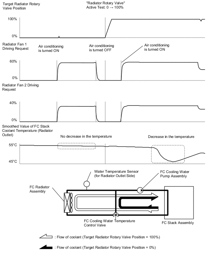
Using Active Tests, set the "Radiator Rotary Valve" to 0%, and check the "Smoothed Value of FC Stack Coolant Temperature (Radiator Outlet)" by turning the air conditioning ON (Lo/Cool Max, maximum airflow) for 1 minute and then turning it OFF for 1 minute.
- Result 1
-
The "Smoothed Value of FC Stack Coolant Temperature (Radiator Outlet)" does not change when the air conditioning is in ON or OFF.
Tech Tips
Turn on the air conditioning to actuate the radiator fan.
-
Using Active Tests, set the "Radiator Rotary Valve" to 100%, and check the "Smoothed Value of FC Stack Coolant Temperature (Radiator Outlet)" by turning the air conditioning ON (Lo/Cool Max, maximum airflow) for 1 minute and then turning it OFF for 1 minute.
- Result 2
-
The "Smoothed Value of FC Stack Coolant Temperature (Radiator Outlet)" changes by 2°C (36°F) or more (increases/decreases) when the air conditioning is turned ON or OFF.
Figure 1. Reference examples
-
Check that the FC cooling water temperature control valve operation is normal by examining the changes in the Smoothed Value of "FC Stack Coolant Temperature (Radiator Outlet)" and inspection results 1 and 2 instructed above.
-
Figure 2. 1. Hydrogen Injector (Shift lever is in P, power switch on (READY), "FC Mode" in the Data List shows FC Working, and "FC Intermittent Operation" shows OFF)
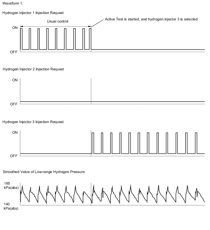
Tech Tips
-
Using an Active Test of the hydrogen injectors, select an injector to operate. Valve opening of a hydrogen injector can be identified by an increase in the "Smoothed Value of Low-range Hydrogen Pressure" when an injection request flag has turned ON.
-
By selecting the injectors from 1 to 3 in sequence, increases in the "Smoothed Value of Low-range Hydrogen Pressure" values during injection can be compared. However, if the "Smoothed Value of Low-range Hydrogen Pressure" increases or it is excessive when an injection request is inactive, it is suspected that any one of the hydrogen injectors has stuck open.
Figure 3. 2. Hydrogen Pump (Shift lever is in P, power switch on (READY), "FC Mode" in the Data List shows FC Working)
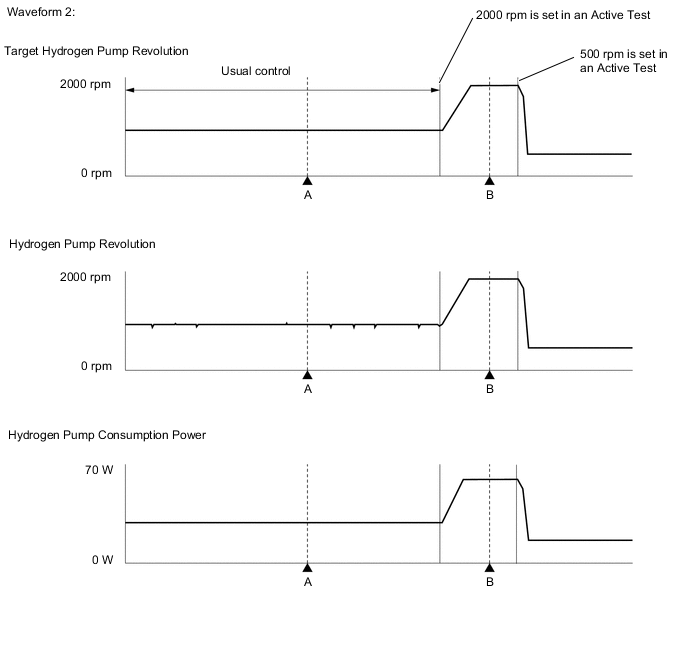
GTS Display Measurement Item Reference value Hydrogen Pump - ▲A ▲B Target Hydrogen Pump Revolution 900 rpm 2013 rpm Hydrogen Pump Revolution 863 rpm 2015 rpm Hydrogen Pump Consumption Power 29 W 69 W Hydrogen Pump Inverter Malfunction OFF OFF Hydrogen Pump Inverter Abnormal Input OFF OFF Hydrogen Pump Inverter Abnormal Loading OFF OFF Tech Tips
-
"Hydrogen Pump Revolution" is normally within a "Target Hydrogen Pump Revolution" +/-200 rpm.
-
The hydrogen pump power consumption is normally within 0 to 100 W.
Figure 4. 3. FC Water Pump (Shift lever is in P, power switch on (READY), "FC Mode" in the Data List shows FC Working)
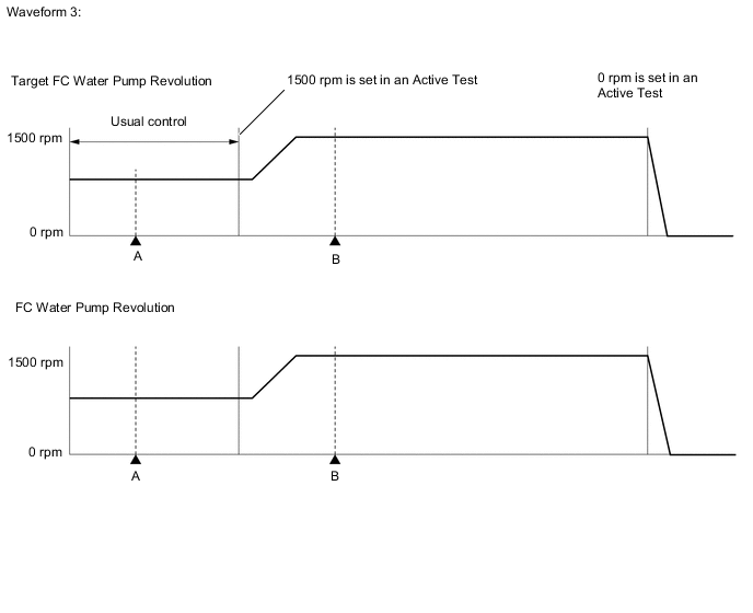
GTS Display Measurement Item Reference value FC Water Pump - ▲A ▲B Target FC Water Pump Revolution 825 rpm 1500 rpm FC Water Pump Revolution 831 rpm 1490 rpm FC Water Pump Inverter Malfunction OFF OFF FC Water Pump Inverter Abnormal Input OFF OFF FC Water Pump Inverter Abnormal Loading OFF OFF Tech Tips
"FC Water Pump Revolution" is normally within a "Target FC Water Pump Revolution" +/-100 rpm
Figure 5. 4. FC Air Compressor (Shift lever is in P, power switch on (READY), "FC Mode" in the Data List shows FC Working)
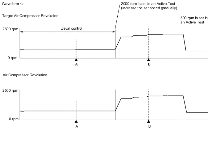
GTS Display Measurement Item Reference value FC Air Compressor - ▲A ▲B Target Air Compressor Revolution 590 rpm 2000 rpm Air Compressor Revolution 575 rpm 1987 rpm Tech Tips
"Air Compressor Revolution" is normally within a "Target Air Compressor Revolution" +/-200 rpm
-