FC CONTROL SYSTEM TERMINALS OF ECU
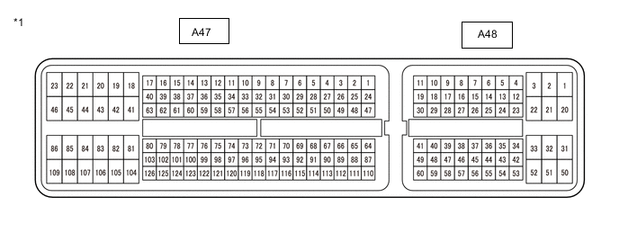
| *1 | FC Control ECU | - | - |
Tech Tips
Because the FC control ECU uses a waterproof connector, voltage, resistance, and waveform inspections are not possible. Voltage, resistance, and waveform information is included for reference.
| Terminal No. (Symbol) | Wiring Color | Terminal Description | Input / Output | Condition | Specified Condition |
|---|---|---|---|---|---|
| A47-38 (ABA1) - A47-45 (E01) | P - W-B | Air shunt valve actuation signal | Output | Power switch on (READY), air shunt valve operated | Pulse generation (Waveform 1) |
| A47-39 (AVB1) - A47-45 (E01) | B - W-B | Air pressure regulating valve actuation signal | Output | Power switch on (READY), air pressure regulating valve operated | Pulse generation (Waveform 2) |
| A47-40 (AVB2) - A47-45 (E01) | W - W-B | Air pressure regulating valve actuation signal | Output | Power switch on (READY), air pressure regulating valve operated | Pulse generation (Waveform 2) |
| A47-41 (VHI3) - A47-46 (E02) | R - W-B | No. 3 hydrogen injector actuation signal | Output | Power switch on (READY), No. 3 hydrogen injector operated | Pulse generation (Waveform 15) |
| A47-42 (HIN2) - A47-46 (E02) | Y - W-B | No. 2 hydrogen injector actuation signal | Output | Power switch on (READY), No. 2 hydrogen injector operated | Pulse generation (Waveform 3) |
| A47-43 (HIN1) - A47-46 (E02) | LG - W-B | No. 1 hydrogen injector actuation signal | Output | Power switch on (READY), No. 1 hydrogen injector operated | Pulse generation (Waveform 4) |
| A47-44 (+BP2) - A47-46 (E02) | B - W-B | Power source | Input | Power switch on (IG) | 11 to 14 V |
| A47-45 (E01) - Body ground | W-B - Body ground | Ground | - | Always | Below 1 Ω |
| A47-46 (E02) - Body ground | W-B - Body ground | Ground | - | Always | Below 1 Ω |
| A47-51 (HDTN) - A48-3 (E1) | Y - W-B | Hydrogen detector (for hydrogen tank side) signal | Input | Power switch on (IG) | Pulse generation (Waveform 5) |
| A47-53 (HDMR) - A48-3 (E1) | SB - W-B | Hydrogen detector (for motor room side) signal | Input | Power switch on (IG) | Pulse generation (Waveform 6) |
| A47-59 (ABB1) - A47-45 (E01) | L - W-B | Air shunt valve actuation signal | Output | Power switch on (READY), air shunt valve operated | Pulse generation (Waveform 1) |
| A47-60 (ABB2) - A47-45 (E01) | Y - W-B | Air shunt valve actuation signal | Output | Power switch on (READY), air shunt valve operated | Pulse generation (Waveform 1) |
| A47-61 (ABA2) - A47-45 (E01) | V - W-B | Air shunt valve actuation signal | Output | Power switch on (READY), air shunt valve operated | Pulse generation (Waveform 1) |
| A47-62 (AVA1) - A47-45 (E01) | R - W-B | Air pressure regulating valve actuation signal | Output | Power switch on (READY), air pressure regulating valve operated | Pulse generation (Waveform 2) |
| A47-63 (AVA2) - A47-45 (E01) | BE - W-B | Air pressure regulating valve actuation signal | Output | Power switch on (READY), air pressure regulating valve operated | Pulse generation (Waveform 2) |
| A47-64 (VHPM) - A47-87 (GHPM) | B - R | Medium-range hydrogen pressure sensor power source | Output | Power switch on (IG) | 4.5 to 5.5 V |
| A47-65 (APFC) - A47-88 (GAPF) | W - R | FC stack inlet air pressure sensor (turbo pressure sensor) signal | Input | Power switch on (IG) | 0.3 to 3.6 V |
| A47-66 (VHPT) - A47-89 (GHPT) | B - R | Hydrogen tank pressure sensor (for outlet side) power source | Output | Power switch on (IG) | 4.5 to 5.5 V |
| A47-74 (AFMF) - A47-98 (GAFF) | B - W | Mass air flow meter signal (airflow sensor) | Input | Power switch on (IG) | Pulse generation (Waveform 16) |
| A47-79 (PIBM) - A48-3 (E1) | L - W-B | EV control ECU wakeup signal | Output | Power switch off | 11 to 14 V |
| A47-81 (HIR3) - A47-46 (E02) | W - W-B | No. 3 hydrogen injector actuation signal (for current resistance circuit) | Output | Power switch on (READY), No. 3 hydrogen injector operated | Pulse generation (Waveform 15) |
| A47-82 (VHI2) - A47-46 (E02) | L - W-B | No. 2 hydrogen injector actuation signal | Output | Power switch on (READY), No. 2 hydrogen injector operated | Pulse generation (Waveform 3) |
| A47-83 (VHI1) - A47-46 (E02) | P - W-B | No. 1 hydrogen injector actuation signal | Output | Power switch on (READY), No. 1 hydrogen injector operated | Pulse generation (Waveform 4) |
| A47-85 (E2) - Body ground | W-B - Body ground | Ground | - | Always | Below 1 Ω |
| A47-87 (GHPM) - Body ground | R - Body ground | Ground | - | Always | Below 1 Ω |
| A47-88 (GAPF) - Body ground | R - Body ground | Ground | - | Always | Below 1 Ω |
| A47-89 (GHPT) - Body ground | R - Body ground | Ground | - | Always | Below 1 Ω |
| A47-90 (GHPL) - Body ground | R - Body ground | Ground | - | Always | Below 1 Ω |
| A47-91 (HPL) - A47-90 (GHPL) | W - R | Low-range hydrogen pressure sensor signal | Input | Power switch on (IG) | 0.5 to 4.5 V |
| A47-93 (HTM) - A47-116 (GHTM) | B - W | Hydrogen pump motor temperature sensor signal | Input | Power switch on (IG), hydrogen pump motor temperature 20°C (68°F) | 4.2 to 4.6 V |
| A47-95 (WTO) - A47-118 (GWTO) | R - G | Water temperature sensor (for FC stack outlet side) signal | Input | Power switch on (IG), FC coolant temperature 20°C (68°F) | 2.1 to 2.7 V |
| A47-97 (GAFT) - Body ground | G - Body ground | Ground | - | Always | Below 1 Ω |
| A47-98 (GAFF) - Body ground | W - Body ground | Ground | - | Always | Below 1 Ω |
| A47-100 (CTF-) - A48-3 (E1) | G - W-B | Communication signal from cell monitor to FC control ECU | Input | Power switch on (READY), cell monitor in communication | Pulse generation (Waveform 17) |
| A47-104 (HIN3) - A47-46 (E02) | G - W-B | No. 3 hydrogen injector actuation signal | Output | Power switch on (READY), No. 3 hydrogen injector operated | Pulse generation (Waveform 15) |
| A47-105 (HVP) - A47-45 (E01) | R - W-B | Exhaust drainage valve actuation signal | Input | Power switch on (READY), exhaust drainage valve operated | Pulse generation (Waveform 7) |
| A47-106 (VHVP) - A47-45 (E01) | W - W-B | Exhaust drainage valve actuation signal | Output | Power switch on (READY), exhaust drainage valve operated | Pulse generation (Waveform 7) |
| A47-107 (+BP1) - A47-45 (E01) | B - W-B | Power source | Input | Power switch on (IG) | 11 to 14 V |
| A47-110 (HPM) - A47-87 (GHPM) | W - R | Medium-range hydrogen pressure sensor signal | Input | Power switch on (IG) | 0.5 to 4.5 V |
| A47-111 (VAPF) - A47-88 (GAPF) | B - R | FC stack inlet air pressure sensor (turbo pressure sensor) power source | Output | Power switch on (IG) | 4.5 to 5.5 V |
| A47-112 (HPT) - A47-89 (GHPT) | W - R | Hydrogen tank pressure sensor (for outlet side) signal | Input | Power switch on (IG) | 0.8 to 4.4 V |
| A47-113 (VHPL) - A47-90 (GHPL) | B - R | Low-range hydrogen pressure sensor power source | Output | Power switch on (IG) | 4.5 to 5.5 V |
| A47-116 (GHTM) - Body ground | W - Body ground | Ground | - | Always | Below 1 Ω |
| A47-118 (GWTO) - Body ground | G - Body ground | Ground | - | Always | Below 1 Ω |
| A47-120 (AFMT) - A47-97 (GAFT) | R - G | Mass air flow meter (intake air temperature sensor) signal | Input | Power switch on (IG), intake air temperature 20°C (68°F) | 2.2 to 2.6 V |
| A47-123 (CTF+) - A48-3 (E1) | R - W-B | Communication signal from cell monitor to FC control ECU | Input | Power switch on (READY), cell monitor in communication | Pulse generation (Waveform 17) |
| A47-125 (CMSP) - A48-3 (E1) | GR - W-B | Cell monitor sleep command | Output | Power switch on (READY), cell monitor in communication | 4.5 to 5.5 V |
| A48-1 (+B1) - A48-3 (E1) | B - W-B | Power source | Input | Power switch on (IG) | 11 to 14 V |
| A48-3 (E1) - Body ground | W-B - Body ground | Ground | - | Always | Below 1 Ω |
| A48-4 (WFN1) - A48-3 (E1) | LG - W-B | Cooling fan controller with motor (for Fan Side) signal | Output | Power switch on (IG), cooling fan controller with motor (for Fan Side) operated | Pulse generation (Waveform 8) |
| A48-8 (CA1H) - A48-3 (E1) | B - W-B | CAN communication signal | Input / Output | Power switch on (IG) | Pulse generation (Waveform 11) |
| A48-9 (CA1L) - A48-3 (E1) | W - W-B | CAN communication signal | Input / Output | Power switch on (IG) | Pulse generation (Waveform 11) |
| A48-10 (CF1H) - A48-3 (E1) | B - W-B | CAN communication signal | Input / Output | Power switch on (IG) | Pulse generation (Waveform 10) |
| A48-11 (CF1L) - A48-3 (E1) | W - W-B | CAN communication signal | Input / Output | Power switch on (IG) | Pulse generation (Waveform 10) |
| A48-12 (WFN2) - A48-3 (E1) | P - W-B | Cooling fan controller with motor (for No. 2 Fan Side) signal | Output | Power switch on (IG), cooling fan controller with motor (for No. 2 Fan Side) operated | Pulse generation (Waveform 9) |
| A48-20 (+B2) - A48-3 (E1) | B - W-B | Power source | Input | Power switch on (IG) | 11 to 14 V |
| A48-23 (BATT) - A48-3 (E1) | B - W-B | Constant power source | Input | Power switch off | 11 to 14 V |
| A48-26 (HSTB) - A48-3 (E1) | BR - W-B | Hydrogen pump inverter actuation signal | Output | Power switch on (READY), hydrogen pump inverter stopped | 4.5 to 5.5 V |
| A48-27 (WSB1) - A48-3 (E1) | V - W-B | FC water pump inverter actuation signal | Output | Power switch on (READY), FC water pump inverter stopped | 4.5 to 5.5 V |
| A48-30 (RLFC) - A48-3 (E1) | L - W-B | FC-IGCT relay signal | Output | Power switch on (IG) | 11 to 14 V |
| A48-31 (WRB1) - A48-3 (E1) | L - W-B | FC cooling water temperature control valve actuation signal | Output | Power switch on (READY), FC cooling water temperature control valve operated | Pulse generation (Waveform 12) |
| A48-32 (WRA1) - A48-3 (E1) | R - W-B | FC cooling water temperature control valve actuation signal | Output | Power switch on (READY), FC cooling water temperature control valve operated | Pulse generation (Waveform 12) |
| A48-33 (RLF2) - A48-3 (E1) | SB - W-B | FC PWR2 relay signal | Output | Power switch on (IG) | 11 to 14 V |
| A48-37 (HCLK) - A48-3 (E1) | W - W-B | Hydrogen pump inverter communication clock signal | Input | Power switch on (READY), hydrogen pump inverter operated | Pulse generation (Waveform 13) |
| A48-38 (HETI) - A48-3 (E1) | Y - W-B | Hydrogen pump inverter communication signal | Output | Power switch on (READY), hydrogen pump inverter operated | Pulse generation (Waveform 13) |
| A48-39 (WEI1) - A48-3 (E1) | L - W-B | FC water pump inverter communication signal | Output | Power switch on (READY), FC water pump inverter operated | Pulse generation (Waveform 14) |
| A48-43 (IG2) - A48-3 (E1) | W - W-B | Power source | Input | Power switch on (IG) | 11 to 14 V |
| A48-47 (WIE1) - A48-3 (E1) | P - W-B | FC water pump inverter communication signal | Input | Power switch on (READY), FC water pump inverter operated | Pulse generation (Waveform 14) |
| A48-48 (WCK1) - A48-3 (E1) | R - W-B | FC water pump inverter communication clock signal | Input | Power switch on (READY), FC water pump inverter operated | Pulse generation (Waveform 14) |
| A48-49 (HITE) - A48-3 (E1) | GR - W-B | Hydrogen pump inverter communication signal | Input | Power switch on (READY), hydrogen pump inverter operated | Pulse generation (Waveform 13) |
| A48-50 (WRB2) - A48-3 (E1) | W - W-B | FC cooling water temperature control valve actuation signal | Output | Power switch on (READY), FC cooling water temperature control valve operated | Pulse generation (Waveform 12) |
| A48-51 (WRA2) - A48-3 (E1) | G - W-B | FC cooling water temperature control valve actuation signal | Output | Power switch on (READY), FC cooling water temperature control valve operated | Pulse generation (Waveform 12) |
| A48-52 (RLFM) - A48-3 (E1) | B - W-B | RDI FAN relay 1, 2 signal | Output | Power switch on (IG) | 11 to 14 V |
| A48-56 (ATIC) - A48-57 (GATI) | G - BE | FC gas temperature sensor signal | Input | Power switch on (IG), intake air temperature 20°C (68°F) | 4.3 to 4.7 V |
| A48-57 (GATI) - Body ground | BE - Body ground | Ground | - | Always | Below 1 Ω |
| A48-59 (GWTR) - Body ground | G - Body ground | Ground | - | Always | Below 1 Ω |
| A48-60 (WTR) - A48-59 (GWTR) | R - G | Water temperature sensor (for radiator outlet side) signal | Input | Power switch on (IG), FC coolant temperature 20°C (68°F) | 2.1 to 2.7 V |
-
Oscilloscope waveforms
Tech Tips
Oscilloscope waveform samples are provided here for informational purposes. Noise and fluttering waveforms have been omitted.
-
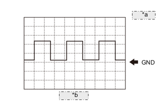
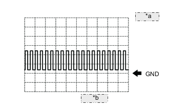
*a 5 V/DIV. *b 10 ms/DIV. Waveform 1
Air shunt valve actuation signal Item Content Terminal ABA1 - E01
ABB1 - E01
ABB2 - E01
ABA2 - E01
Equipment Setting 5 V/DIV., 10 ms/DIV. Condition Power switch on (READY), air shunt valve operated Tech Tips
-
The waveform shown in the illustration may not be generated depending on the conditions.
-
The waveform cycle may vary depending on the conditions.
-
-
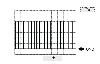
*a 5 V/DIV. *b 10 ms/DIV. Waveform 2
Air pressure regulating valve actuation signal Item Content Terminal AVB1 - E01
AVB2 - E01
AVA1 - E01
AVA2 - E01
Equipment Setting 5 V/DIV., 10 ms/DIV. Condition Power switch on (READY), air pressure regulating valve operated Tech Tips
-
The waveform shown in the illustration may not be generated depending on the conditions.
-
The waveform cycle may vary depending on the conditions.
-
-
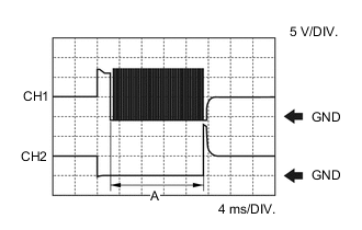
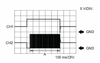
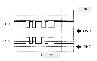
Waveform 3
No. 2 hydrogen injector actuation signal Item Content Terminal CH1: VHI2 - E02
CH2: HIN2 - E02
Equipment Setting 5 V/DIV., 4 ms/DIV. Condition Power switch on (READY), No. 2 hydrogen injector operated Tech Tips
-
The waveform shown in the illustration may not be generated depending on the conditions.
-
The time in range A may vary depending on the conditions.
-
-
Waveform 4
No. 1 hydrogen injector actuation signal Item Content Terminal CH1: VHI1 - E02
CH2: HIN1 - E02
Equipment Setting 5 V/DIV., 4 ms/DIV. Condition Power switch on (READY), No. 1 hydrogen injector operated Tech Tips
-
The waveform shown in the illustration may not be generated depending on the conditions.
-
The time in range A may vary depending on the conditions.
-
-
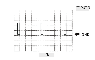
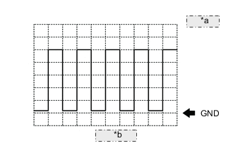
*a 5 V/DIV. *b 1 ms/DIV. Waveform 5
Hydrogen detector (for hydrogen tank side) signal Item Content Terminal HDTN - E1 Equipment Setting 5 V/DIV., 1 ms/DIV. Condition Power switch on (IG) Tech Tips
The duty ratio may vary depending on the conditions.
-
*a 5 V/DIV. *b 1 ms/DIV. Waveform 6
Hydrogen detector (for motor room side) signal Item Content Terminal HDMR - E1 Equipment Setting 5 V/DIV., 1 ms/DIV. Condition Power switch on (IG) Tech Tips
The duty ratio may vary depending on the conditions.
-
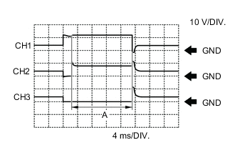
Waveform 7
Exhaust drainage valve actuation signal Item Content Terminal CH1: VHVP - E01
CH2: HVP - E01
Equipment Setting 5 V/DIV., 100 ms/DIV. Condition Power switch on (READY), exhaust drainage valve operated Tech Tips
-
The waveform shown in the illustration may not be generated depending on the conditions.
-
The time in range A may vary depending on the conditions.
-
-
*a 1 V/DIV. *b 20 ms/DIV. Waveform 8
Cooling fan controller with motor (for Fan Side) signal Item Content Terminal WFN1 - E1 Equipment Setting 1 V/DIV., 20 ms/DIV. Condition Power switch on (IG), cooling fan controller with motor (for Fan Side) operated -
*a 1 V/DIV. *b 20 ms/DIV. Waveform 9
Cooling fan controller with motor (for No. 2 Fan Side) signal Item Content Terminal WFN2 - E1 Equipment Setting 1 V/DIV., 20 ms/DIV. Condition Power switch on (IG), cooling fan controller with motor (for No. 2 Fan Side) operated -
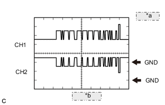
*a 1 V/DIV. *b 50 μs/DIV. Waveform 10
CAN communication signal Item Content Terminal CH1: CF1H - E1
CH2: CF1L - E1
Equipment Setting 1 V/DIV., 50 μs/DIV. Condition Power switch on (IG) Tech Tips
The waveform will vary depending on the content of the digital communication (digital signal).
-
*a 1 V/DIV. *b 50 μs/DIV. Waveform 11
CAN communication signal Item Content Terminal CH1: CA1H - E1
CH2: CA1L - E1
Equipment Setting 1 V/DIV., 50 μs/DIV. Condition Power switch on (IG) Tech Tips
The waveform will vary depending on the content of the digital communication (digital signal).
-
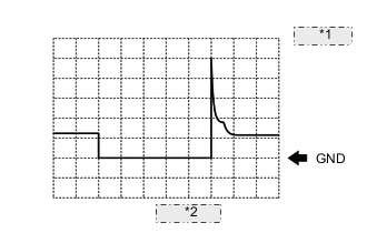
*1 20 V/DIV. *2 10 ms/DIV. Waveform 12
FC cooling water temperature control valve actuation signal Item Content Terminal WRB1 - E1
WRA1 - E1
WRB2 - E1
WRA2 - E1
Equipment Setting 20 V/DIV., 10 ms/DIV. Condition Power switch on (READY), FC cooling water temperature control valve operated -
*a 1 V/DIV. *b 100 ms/DIV. Waveform 13
Hydrogen pump inverter communication signal Item Content Terminal CH1: HCLK - E1
CH2: HITE - E1
CH3: HETI - E1
Equipment Setting 1 V/DIV., 100 ms/DIV. Condition Power switch on (READY), hydrogen pump inverter operated Tech Tips
The waveform will vary depending on the content of the digital communication (digital signal).
-
*a 1 V/DIV. *b 100 ms/DIV. Waveform 14
FC water pump inverter communication signal Item Content Terminal CH1: WCK1 - E1
CH2: WIE1 - E1
CH3: WEI1 - E1
Equipment Setting 1 V/DIV., 100 ms/DIV. Condition Power switch on (READY), FC water pump inverter operated Tech Tips
The waveform will vary depending on the content of the digital communication (digital signal).
-
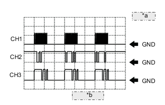
Waveform 15
No. 3 hydrogen injector actuation signal Item Content Terminal CH1: VHI3 - E02
CH2: HIN3 - E02
CH3: HIR3 - E02
Equipment Setting 10 V/DIV., 4 ms/DIV. Condition Power switch on (READY), No. 3 hydrogen injector operated Tech Tips
-
The waveform shown in the illustration may not be generated depending on the conditions.
-
The time in range A may vary depending on the conditions.
-
-
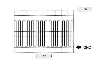
*a 1 V/DIV. *b 1 ms/DIV. Waveform 16
Mass air flow meter signal (airflow sensor) Item Content Terminal AFMF - GAFF Equipment Setting 1 V/DIV., 1 ms/DIV. Condition Power switch on (IG) Tech Tips
The frequency increases when the flowing air amount increases.
-
*a 1 V/DIV. *b 100 μs/DIV. Waveform 17
Communication signal from cell monitor to FC control ECU Item Content Terminal CH1: CTF+ - E1
CH2: CTF- - E1
Equipment Setting 1 V/DIV., 100 μs/DIV. Condition Power switch on (READY), cell monitor in communication Tech Tips
The waveform will vary depending on the content of the digital communication (digital signal).

*1 Hydrogen Fuel Control ECU Assembly - - Hydrogen Fuel Control ECU Assembly Terminal No. (Symbol) Wiring Color Terminal Description Input / Output Condition Specified Condition P30-1 (GTV1) - Body ground W-B - Body ground Ground - Always Below 1 Ω P30-2 (GTV2) - Body ground W-B - Body ground Ground - Always Below 1 Ω P30-3 (TNV2) - P30-2 (GTV2) B - W-B Tank shut valve 2 actuation signal Input Power switch on (READY), tank shut valve 2 open Pulse generation
(Waveform 2)
P30-5 (+BP) - P30-10 (E1) B - W-B Tank shut valve 1,2 power source Output Power switch on (READY) 11 to 14 V P30-6 (TNV1) - P30-1 (GTV1) B - W-B Tank shut valve 1 actuation signal Input Power switch on (READY), tank shut valve 1 open Pulse generation
(Waveform 3)
P30-7 (RLLO) - P30-10 (E1) Y - W-B FUEL OPN NO.1 relay signal Input At moment of fuel lid lock actuation 11 to 14 V P30-8 (LOSW) - P30-10 (E1) R - W-B Fuel lid opener switch signal Input Fuel lid opener switch off 11 to 14 V P30-10 (E1) - Body ground W-B - Body ground Ground - Always Below 1 Ω P30-11 (GHPC) - Body ground R - Body ground Ground - Always Below 1 Ω P30-12 (VHPC) - P30-10 (E1) B - W-B Hydrogen tank pressure sensor (for inlet side) power source Output Power switch on (IG) 4.75 to 5.25 V P30-14 (RLL2) - P30-10 (E1) P - W-B FUEL OPN NO. 2 relay signal Input At moment of fuel lid unlock actuation 11 to 14 V P30-15 (CAFH) - P30-10 (E1) SB - W-B CAN communication signal Input / Output Power switch on (IG) Pulse generation
(Waveform 1)
P30-16 (CAFL) - P30-10 (E1) W - W-B CAN communication signal Input / Output Power switch on (IG) Pulse generation
(Waveform 1)
P30-20 (VSEO) - P30-22 (GSEO) B - R Hydrogen fuel control transmitter power source Output Power switch on (IG) 4.9 to 5.8 V P30-21 (SEO) - P30-22 (GSEO) W - R Hydrogen fuel control transmitter signal Output As fuel lid is opening Pulse generation
(Waveform 4)
P30-22 (GSEO) - Body ground R - Body ground Ground - Always Below 1 Ω P30-23 (FILK) - P30-10 (E1) G - W-B Fuel filler opening lid sub assembly (hinge switch) signal Output Fuel lid fully open 11 to 14 V P30-25 (FIL2) - P30-10 (E1) GR - W-B Fuel filler opening lid switch sub-assembly signal Output Fuel lid fully closed 11 to 14 V P30-27 (GTT1) - Body ground BR - Body ground Ground - Always Below 1 Ω P30-28 (TNT1) - P30-27 (GTT1) Y - BR Hydrogen tank temperature sensor 1 signal Output Power switch on (IG) 1.0 to 2.8 V
(1.78 V (20°C (68°F))
P30-29 (GTT2) - Body ground P - Body ground Ground - Always Below 1 Ω P30-30 (TNT2) - P30-29 (GTT2) L - P Hydrogen tank temperature sensor 2 signal Output Power switch on (IG) 1.0 to 2.8 V
(1.78 V (20°C (68°F))
P30-32 (HPC) - P30-11 (GHPC) W - R Hydrogen tank pressure sensor (for inlet side) signal Output Power switch on (IG) 0.5 to 4.8 V P30-36 (IGSW) - P30-10 (E1) B - W-B Power source Input Power switch on (IG) 11 to 14 V P30-37 (BATT) - P30-10 (E1) R - W-B Constant power source Input Always 11 to 14 V -
-
Oscilloscope waveforms
Tech Tips
Oscilloscope waveform samples are provided here for informational purposes. Noise and fluttering waveforms have been omitted.
-
*a 1 V/DIV. *b 50 μs/DIV. Waveform 1
CAN communication signal Item Content Terminal CH1: CAFH - E1
CH2: CAFL - E1
Equipment Setting 1 V/DIV., 50 μs/DIV. Condition Power switch on (IG) Tech Tips
The waveform will vary depending on the content of the digital communication (digital signal).
-
*a 5 V/DIV. *b 1 ms/DIV. Waveform 2
Tank shut valve 2 actuation signal Item Content Terminal TNV2 - GTV2 Equipment Setting 5 V/DIV., 1 ms/DIV. Condition Power switch on (READY), tank shut valve 2 open -
*a 5 V/DIV. *b 1 ms/DIV. Waveform 3
Tank shut valve 1 actuation signal Item Content Terminal TNV1 - GTV1 Equipment Setting 5 V/DIV., 1 ms/DIV. Condition Power switch on (READY), tank shut valve 1 open -
*a 1 V/DIV. *b 100 μs/DIV. Waveform 4
Hydrogen fuel control transmitter signal Item Content Terminal SEO - GSEO Equipment Setting 1 V/DIV., 100 μs/DIV. Condition As fuel lid is opening Tech Tips
The waveform will vary depending on the content of the digital communication (digital signal).
-