FC CONTROL SYSTEM, Diagnostic DTC:P1DCF-450
| DTC Code | DTC Name |
|---|---|
| P1DCF-450 | Cell Monitor Performance |
DESCRIPTION
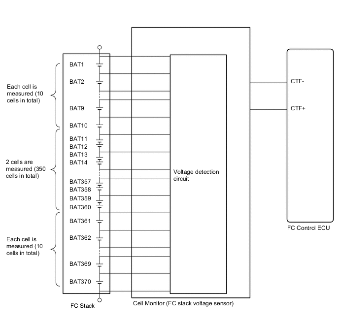
The FC stack consists of 370 cells that are connected in series. In order to measure a voltage at both ends of the FC stack cells individually or as a pair, the cell monitor is constructed as shown in the illustration below.
The cell monitor measures a voltage for each cell, and always monitors the power generated by the cells individually or as a pair (all cells are monitored individually using estimated values). When a generated power voltage deviates from an appropriate range, it forces the FC control ECU to apply feedback control to each of the hydrogen, air and cooling systems.
If the cell monitor finds an error in the microcomputer itself, or abnormalities in the cell monitor power voltage, it informs the FC control ECU of such information, causing the FC control ECU to set this DTC.
| DTC No. | Detection Item | DTC Detection Condition | Trouble Area | Warning Indicate |
|---|---|---|---|---|
| P1DCF-450 | Cell Monitor Performance | If the cell monitor detects malfunctions in the cell monitor itself, or abnormalities in the cell monitor circuit, it transmits a signal to the FC control ECU. This self diagnosis is always active while power is being generated except for when the cell monitor is in sleep mode. The cell monitor watches the performance by measuring an output from each 1 or 2 of the 370 cells in the FC stack. Upon receiving a signal from the cell monitor, the FC control ECU interprets that the cell monitor is unable to monitor the cells. (1 trip detection logic) |
|
Master Warning Light: Comes on |
| Vehicle Condition | FC shutdown (power switch on (IG)) |
FC startup process | FC intermittent operation | FC is generating power (vehicle is in stationary) |
FC is generating power (vehicle is traveling) |
FC shutdown process |
|---|---|---|---|---|---|---|
| Data List "FC Mode" |
FC Shutdown | FC Startup Process | FC Working | FC Shutdown Process | ||
| Data List "FC Intermittent Operation" |
OFF | ON | OFF | OFF | ||
| DTC Detection | - | - | ○ | ○ | ○ | - |
| DTC No. | Data List |
|---|---|
| P1DCF-450 |
|
The following items can be helpful when performing repairs:
-
Battery Voltage
Data List
-
Vehicle Speed
-
Shift Sensor Shift Position
-
Accelerator Degree
-
Ready
-
FC Mode
-
FC Intermittent Operation
-
FC Voltage before Boosting
-
FC Current
-
Target Low-range Hydrogen Pressure
-
Smoothed Value of Low-range Hydrogen Pressure
-
Target Hydrogen Pump Revolution
-
Hydrogen Pump Revolution
-
Target FC Stack Air Pressure (FC Stack Inlet)
-
Smoothed Value of FC Stack Air Pressure (FC Stack Inlet)
-
Target Mass Air Flow Value
-
Mass Air Flow Value
-
Target Air Compressor Revolution
-
Air Compressor Revolution
-
Target FC Stack Coolant Temperature (FC Stack Outlet)
-
Smoothed Value of FC Stack Coolant Temperature (FC Stack Outlet)
-
Exhaust Drainage Valve Driving Request
Common Data List items for FC inspection
| DTC No. | Active Test |
|---|---|
| P1DCF-450 | Cell Monitor Control |
CAUTION / NOTICE / HINT
CAUTION:
-


Before the following operations are conducted, take precautions to prevent electric shock by turning the power switch off, wearing insulated gloves, and removing the service plug grips from both FC stack assembly and EV battery.
-
Inspecting the high-voltage system
-
Disconnecting the low voltage connector of the inverter with converter assembly
-
Disconnecting the low voltage connector of the EV battery
-
Disconnecting the low voltage connector of the FC stack assembly
-
Disconnecting the low voltage connector of the FC converter assembly
-
Tech Tips
No removal order is specified for the service plug grips of the FC stack assembly and EV battery.
-

After removing the service plug grip from the EV battery, put it in your pocket to prevent other technicians from accidentally reconnecting it while you are working on the high-voltage system. After removing the service grip from the FC stack assembly, store it in a safe location and use the "HIGH-VOLTAGE, DO NOT TOUCH" sign to notify other technicians that you are working on the high-voltage system.
-

*a Without waiting for 10 minutes After removal of the service plug grips of both FC stack assembly and EV battery, wait for at least 10 minutes before touching the high-voltage connectors and terminals. After waiting for 10 minutes, check the voltage at the terminals in the inspection point in the inverter with converter assembly. The voltage should be 0 V before beginning work.
Tech Tips
At least 10 minutes are necessary to discharge the high-voltage capacitors inside the inverter with converter assembly and FC stack assembly.
Note
-
When reinstalling the service plug grip to the FC stack assembly or the EV battery, slide the lever of the service plug until the letters "UNLOCK" are completely hidden, and insert it firmly.
-
When the vehicle is parked with the power switch off, if the FC control ECU judges that the FC stack temperature will go below 0°C (32°F), it activates the FC air compressor, hydrogen pump and FC cooling water pump for a maximum of 180 seconds and drains water from the FC stack assembly. When performing inspection or repairs with the power switch off (not on (IG) or on (READY)), disconnect the cable from the negative (-) auxiliary battery terminal before performing work (If the auxiliary battery voltage is needed to conduct inspection, warm up the FC system beforehand).
Tech Tips
-
Forcing the SOC of the EV battery to decrease by applying electrical loads such as turning on the air conditioning (HOT MAX, maximum airflow), or depressing the accelerator pedal with the shift lever in P, the "FC Intermittent Operation" of the Data List is easily to enter OFF (power generation mode).
After the repair, clear the DTCs and perform the following procedure to check that DTCs are not output.
-
Connect the GTS to the DLC3.
-
Turn the power switch on (IG).
-
Using the GTS, check that all of the Data List items listed below are OFF.
-
Cell Monitor Power Voltage Low
-
Cell Monitor Voltage Exceed Upper Limit
-
Cell Monitor Block Voltage Low
-
Cell Monitor Voltage Reversal
-
Cell Monitor EEPROM Malfunction
-
Cell Monitor RAM Malfunction
-
Cell Monitor ROM Malfunction
-
Cell Monitor AD Malfunction
-
Cell Monitor Multiplying and Dividing Circuit Malfunction
-
Cell Monitor Offset Malfunction
-
Turn the "Cell Monitor Control" Active Test to OFF, and wait for 30 seconds.
-
Turn the power switch on (READY) with the shift lever in P, and wait for at least 2 minutes. If no DTCs are set in this step, drive the vehicle in city streets for approximately 10 minutes by referring to the applicable freeze frame data (Vehicle Speed, Accelerator Degree, etc.).
CAUTION:
Perform this road test only in an appropriate safe location, in accordance with all local laws.
PROCEDURE
-
CHECK FREEZE FRAME DATA
Note
The freeze frame data is cleared when DTCs are cleared. Be sure to make a note of necessary data in advance.
-
Connect the GTS to the DLC3.
-
Turn the power switch on (IG).
-
Turn the GTS on.
-
Enter the following menus: Powertrain / FC / Trouble Codes.
-
Read the freeze frame data of DTC P1DCF-450.
Table 1 Cell Monitor Voltage Exceed Upper Limit Cell Monitor EEPROM Malfunction Cell Monitor RAM Malfunction Cell Monitor ROM Malfunction Cell Monitor AD Malfunction Cell Monitor Multiplying and Dividing Circuit Malfunction Result Result Proceed to Any one of the freeze frame data items listed in table 1 above indicates ON A The "Cell Monitor Offset Malfunction" of the freeze frame data shows ON B The "Cell Monitor Power Voltage Low" of the freeze frame data shows ON C The "Cell Monitor Block Voltage Low" or "Cell Monitor Voltage Reversal" of the freeze frame data shows ON D -
Turn the power switch off.
A 
GO TO STEP 17 Click here
C
CHECK TERMINAL VOLTAGE (POWER SOURCE OF FC STACK ASSEMBLY (CELL MONITOR)) Click here
D
CHECK DTC OUTPUT Click here
B 
-
-
CLEAR DTC
-
Connect the GTS to the DLC3.
-
Turn the power switch on (IG).
-
Turn the GTS on.
-
Enter the following menus: Powertrain / FC / Trouble Codes.
-
Clear the DTCs.
Powertrain > FC > Clear DTCs -
Turn the power switch off and wait for 3 minutes or more.
Result Proceed to NEXT
NEXT
-
-
READ VALUE USING GTS
-
Connect the GTS to the DLC3.
-
Turn the power switch on (IG).
-
Turn the GTS on.
-
Enter the following menus: Powertrain / FC / Data List / Cell Monitor Power Voltage Low, Cell Monitor Voltage Exceed Upper Limit, Cell Monitor Block Voltage Low, Cell Monitor Voltage Reversal, Cell Monitor EEPROM Malfunction, Cell Monitor RAM Malfunction, Cell Monitor ROM Malfunction, Cell Monitor AD Malfunction, Cell Monitor Multiplying and Dividing Circuit Malfunction, Cell Monitor Offset Malfunction
Powertrain > FC > Data ListTester Display Cell Monitor Power Voltage Low Cell Monitor Voltage Exceed Upper Limit Cell Monitor Block Voltage Low Cell Monitor Voltage Reversal Cell Monitor EEPROM Malfunction Cell Monitor RAM Malfunction Cell Monitor ROM Malfunction Cell Monitor AD Malfunction Cell Monitor Multiplying and Dividing Circuit Malfunction Cell Monitor Offset Malfunction -
Read the value displayed on the GTS.
Table 1 Cell Monitor Voltage Exceed Upper Limit Cell Monitor EEPROM Malfunction Cell Monitor RAM Malfunction Cell Monitor ROM Malfunction Cell Monitor AD Malfunction Cell Monitor Multiplying and Dividing Circuit Malfunction Result Result Proceed to Any one of the data list items listed in table 1 above indicates ON A The "Cell Monitor Offset Malfunction" of the data list shows ON B The "Cell Monitor Power Voltage Low" of the data list shows ON C The "Cell Monitor Block Voltage Low" or "Cell Monitor Voltage Reversal" of the data list shows ON D All selected data list items show OFF E -
Turn the power switch off.
A
GO TO STEP 17 Click here
B 
REPLACE FC STACK ASSEMBLY Click here
C
GO TO STEP 5 Click here
D
GO TO STEP 16 Click here
E
-
-
PERFORM ACTIVE TEST USING GTS (CELL MONITOR CONTROL)
-
Connect the GTS to the DLC3.
-
Turn the power switch on (IG).
-
Turn the GTS on.
-
Enter the following menus: Powertrain / FC / Active Test / Cell Monitor Control
-
Select "Cell Monitor Offset Malfunction" in the Data List.
Powertrain > FC > Active TestActive Test Display Cell Monitor Control Data List Display Cell Monitor Offset Malfunction -
Turn the "Cell Monitor Control" Active Test to OFF, and wait for 30 seconds.
-
Check the "Cell Monitor Offset Malfunction" of the data list.
Result Result Proceed to The "Cell Monitor Offset Malfunction" of the data list shows OFF. A The "Cell Monitor Offset Malfunction" of the data list shows ON. B
A
GO TO STEP 19 Click here
B
REPLACE FC STACK ASSEMBLY Click here
-
-
CHECK TERMINAL VOLTAGE (POWER SOURCE OF FC STACK ASSEMBLY (CELL MONITOR))
CAUTION:
Be sure to wear insulated gloves.
-
Check that the service plug grip is not installed to FC stack assembly and EV battery.
Note
After removing the service plug grip, do not turn the power switch on (READY), unless instructed by the repair manual because this may cause a malfunction.
-
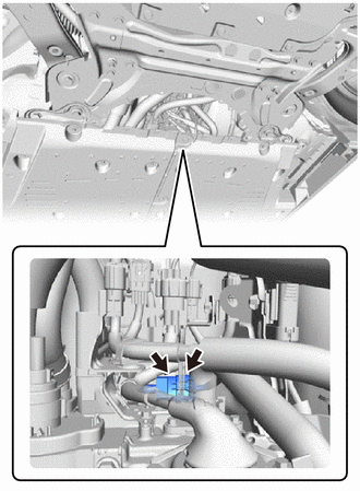
Disconnect the FC stack assembly (Cell monitor) connector.
-
Connect the cable to the negative (-) auxiliary battery terminal.
-
Turn the power switch on (IG).
-
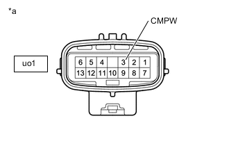
*a Component without harness connected [FC Converter Assembly]
(to FC Stack Assembly (Cell Monitor))
Measure the voltage according to the value(s) in the table below.
Standard Voltage Tester Connection Condition Specified Condition uo1-3 (CMPW) - Body ground Power switch on (IG) 11 to 14 V -
Turn the power switch off.
-
Disconnect the cable from the negative (-) auxiliary battery terminal.
-
Reconnect the FC stack assembly (Cell monitor) connector.
Result Proceed to OK NG
OK
CHECK FOR INTERMITTENT PROBLEMS Click here
NG
-
-
CHECK TERMINAL VOLTAGE (POWER SOURCE OF FC STACK ASSEMBLY (CELL MONITOR))
CAUTION:
Be sure to wear insulated gloves.
-
Check that the service plug grip is not installed to FC stack assembly and EV battery.
Note
After removing the service plug grip, do not turn the power switch on (READY), unless instructed by the repair manual because this may cause a malfunction.
-
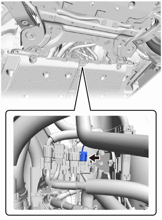
Disconnect the FC converter assembly connector.
-
Connect the cable to the negative (-) auxiliary battery terminal.
-
Turn the power switch on (IG).
-
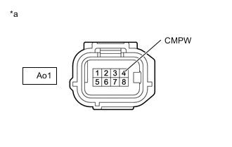
*a Front view of wire harness connector
(to FC Converter Assembly)
Measure the voltage according to the value(s) in the table below.
Standard Voltage Tester Connection Condition Specified Condition Ao1-4 (CMPW) - Body ground Power switch on (IG) 11 to 14 V -
Turn the power switch off.
-
Disconnect the cable from the negative (-) auxiliary battery terminal.
-
Reconnect the FC converter assembly connector.
Result Proceed to OK NG
OK
REPLACE FC CONVERTER ASSEMBLY Click here
NG
-
-
CHECK HARNESS AND CONNECTOR (FC CONVERTER ASSEMBLY - FC-IGCT RELAY)
CAUTION:
Be sure to wear insulated gloves.
-
Check that the service plug grip is not installed to FC stack assembly and EV battery.
Note
After removing the service plug grip, do not turn the power switch on (READY), unless instructed by the repair manual because this may cause a malfunction.
-
Disconnect the FC converter assembly connector.
-
Remove the FC-IGCT relay from the motor compartment relay block.
-
Measure the resistance according to the value(s) in the table below.
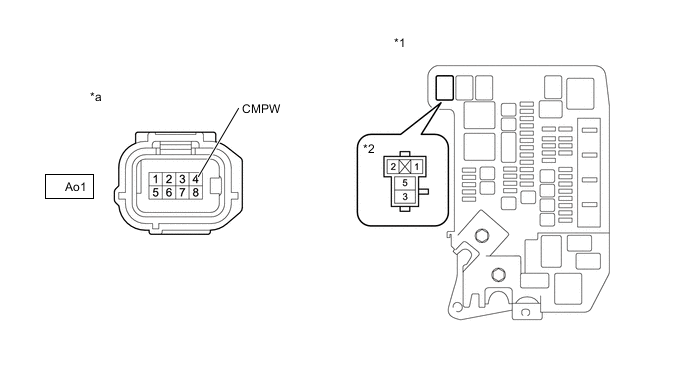
*1 Motor Compartment Relay Block *2 FC-IGCT Relay Holder *a Front view of wire harness connector
(to FC Converter Assembly)
- - Standard Resistance Tester Connection Condition Specified Condition Ao1-4 (CMPW) - 3 (FC-IGCT relay holder) Always Below 1 Ω Ao1-4 (CMPW) or 3 (FC-IGCT relay holder) - Body ground and other terminals Always 10 kΩ or higher Result Proceed to OK NG
NG
REPAIR OR REPLACE HARNESS OR CONNECTOR
OK
-
-
CHECK TERMINAL VOLTAGE (POWER SOURCE OF FC-IGCT RELAY)
-
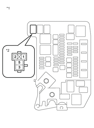
*1 Motor Compartment Relay Block *2 FC-IGCT Relay Holder Remove the FC-IGCT relay from the motor compartment relay block.
-
Turn the power switch on (IG).
-
Measure the voltage according to the value(s) in the table below.
Standard Voltage Tester Connection Condition Specified Condition 1 (FC-IGCT relay holder) - Body ground Power switch on (IG) 11 to 14 V -
Turn the power switch off.
-
Reinstall the FC-IGCT relay.
Result Proceed to OK NG
NG
CHECK HARNESS AND CONNECTOR (FC CONTROL ECU - FC-IGCT RELAY) Click here
OK
-
-
INSPECT RELAY (FC-IGCT)
Result Proceed to OK NG
NG
REPLACE RELAY (FC-IGCT)
OK
-
CHECK HARNESS AND CONNECTOR (FC-IGCT RELAY - BODY GROUND)
-
Remove the FC-IGCT relay from the motor compartment relay block.
-

*1 Motor Compartment Relay Block *2 FC-IGCT Relay Holder Measure the resistance according to the value(s) in the table below.
Standard Resistance Tester Connection Condition Specified Condition 2 (FC-IGCT relay holder) - Body ground Always Below 1 Ω -
Reinstall the FC-IGCT relay.
Result Proceed to OK NG
NG
REPAIR OR REPLACE HARNESS OR CONNECTOR
OK
-
-
CHECK TERMINAL VOLTAGE (POWER SOURCE OF FC-IGCT RELAY)
-

*1 Motor Compartment Relay Block *2 FC-IGCT Relay Holder Remove the FC-IGCT relay from the motor compartment relay block.
-
Measure the voltage according to the value(s) in the table below.
Standard Voltage Tester Connection Condition Specified Condition 5 (FC-IGCT relay holder) - Body ground Power switch off 11 to 14 V -
Reinstall the FC-IGCT relay.
Result Proceed to OK NG
OK
CHECK FOR INTERMITTENT PROBLEMS Click here
NG
REPAIR OR REPLACE HARNESS OR CONNECTOR (FC-IGCT RELAY - AUXILIARY BATTERY)
-
-
CHECK HARNESS AND CONNECTOR (FC CONTROL ECU - FC-IGCT RELAY)
-
Disconnect the FC control ECU connector.
-
Remove the FC-IGCT relay from the motor compartment relay block.
-
Measure the resistance according to the value(s) in the table below.
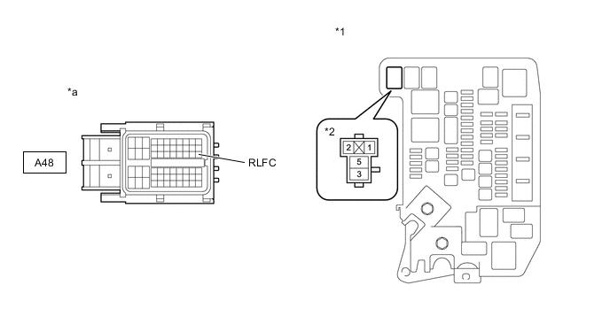
*1 Motor Compartment Relay Block *2 FC-IGCT Relay Holder *a Front view of wire harness connector
(to FC Control ECU)
- - Standard Resistance Tester Connection Condition Specified Condition A48-30 (RLFC) - 1 (FC-IGCT relay holder) Always Below 1 Ω A48-30 (RLFC) or 1 (FC-IGCT relay holder) - Body ground and other terminals Always 10 kΩ or higher -
Reinstall the FC-IGCT relay.
-
Reconnect the FC control ECU connector.
Result Proceed to OK NG
NG
REPAIR OR REPLACE HARNESS OR CONNECTOR
OK
-
-
INSPECT AUXILIARY BATTERY
Result Proceed to OK NG
OK
REPLACE FC CONTROL ECU Click here
NG
-
CHARGE OR REPLACE AUXILIARY BATTERY
-
Charge or replace the auxiliary battery.
Result Proceed to NEXT
NEXT
-
-
CHECK DTC OUTPUT
-
Connect the GTS to the DLC3.
-
Turn the power switch on (IG).
-
Turn the GTS on.
-
Enter the following menus: Powertrain / FC / Trouble Codes.
-
Check for DTCs.
Powertrain > FC > Trouble CodesResult Result Proceed to DTCs are not output A DTC P1DCF-450 is output B
A
CHECK FOR INTERMITTENT PROBLEMS Click here
B
REPLACE FC CONTROL ECU Click here
-
-
CHECK DTC OUTPUT
-
Connect the GTS to the DLC3.
-
Turn the power switch on (IG).
-
Turn the GTS on.
-
Enter the following menus: Powertrain / FC / Trouble Codes.
-
Check for DTCs.
Powertrain > FC > Trouble CodesResult Result Proceed to DTCs are not output A DTC P1DEF-450 is output B
B
GO TO DTC CHART Click here
A
-
-
CLEAR DTC
-
Connect the GTS to the DLC3.
-
Turn the power switch on (IG).
-
Turn the GTS on.
-
Enter the following menus: Powertrain / FC / Trouble Codes.
-
Clear the DTCs.
Powertrain > FC > Clear DTCs -
Turn the power switch off and wait for 3 minutes or more.
Result Proceed to NEXT
NEXT
-
-
CHECK DTC OUTPUT
-
Connect the GTS to the DLC3.
-
Turn the power switch on (IG).
-
Turn the GTS on.
-
Enter the following menus: Powertrain / FC / Data List / FC Mode, FC Intermittent Operation
Powertrain > FC > Data ListTester Display FC Mode FC Intermittent Operation -
Turn the power switch on (READY) with the shift lever in P, and check the Data List that "FC Mode" is FC Working and "FC Intermittent Operation" is OFF. Then, wait for 2 minutes or more.
-
Enter the following menus: Powertrain / FC / Trouble Codes.
-
Check for DTCs.
Powertrain > FC > Trouble CodesResult Result Proceed to DTCs are not output A DTC P1DCF-450 is output* B
-
*: The cell monitor is malfunctioning
-
B
REPLACE FC STACK ASSEMBLY Click here
A
-
-
SIMULATION TEST
-
Connect the GTS to the DLC3.
-
Turn the power switch on (IG).
-
Turn the GTS on.
-
Drive the vehicle for 10 minutes according to the freeze frame data (Vehicle Speed, Accelerator Degree, etc.).
If vehicle speeds, accelerator pedal positions, road conditions, ambient temperatures and climates at the time the malfunction occurred can be determined, take them into account.
CAUTION:
Perform this road test only in an appropriate safe location, in accordance with all local laws.
-
Enter the following menus: Powertrain / FC / Trouble Codes.
-
Check for DTCs.
Powertrain > FC > Trouble CodesResult Result Proceed to DTCs are not output A DTC P1DCF-450 is output* B
-
*: The cell monitor is malfunctioning
-
-
Turn the power switch off.
A
CHECK FOR INTERMITTENT PROBLEMS Click here
B
REPLACE FC STACK ASSEMBLY Click here
-