FC CONTROL SYSTEM, Diagnostic DTC:P1DC5-450
| DTC Code | DTC Name |
|---|---|
| P1DC5-450 | Air Pressure Too High |
DESCRIPTION
The air system of the FC system feeds the FC stack with oxygen, so that the FC stack can generate power.
In order to feed the FC stack with air volume and pressure that are needed for FC stack power generation, the air system regulates the air pressure regulating valve, air shunt valve and FC air compressor with motor assembly based the sensor inputs.
If the air pressure (air pressure sensor measurement) is likely to exceed the FC stack pressure limitation, the FC control ECU interprets that the air pressure is excessively high, and sets this DTC.
For the circuit diagram, refer to DTC P0101-450.
| DTC No. | Detection Item | DTC Detection Condition | Trouble Area | Warning Indicate |
|---|---|---|---|---|
| P1DC5-450 | Air Pressure Too High | FC Stack Air Pressure (FC Stack Inlet) is likely to exceed the FC stack pressure limitation. This malfunction detection is active while the FC system is in modes other than FC Shutdown. (1 trip detection logic) |
|
Master Warning Light: Comes on |
| Vehicle Condition | FC shutdown (power switch on (IG)) |
FC startup process | FC intermittent operation | FC is generating power (vehicle is in stationary) |
FC is generating power (vehicle is traveling) |
FC shutdown process |
|---|---|---|---|---|---|---|
| Data List "FC Mode" |
FC Shutdown | FC Startup Process | FC Working | FC Shutdown Process | ||
| Data List "FC Intermittent Operation" |
OFF | ON | OFF | OFF | ||
| DTC Detection | - | ○ | ○ | ○ | ○ | ○ |
| DTC No. | Data List |
|---|---|
| P1DC5-450 |
|
The following items can be helpful when performing repairs:
-
Target Air Shunt Valve Position
-
Target Air Pressure Regulating Valve Position
-
Target Air Compressor Revolution
-
Air Compressor Revolution
-
Target Mass Air Flow Value
-
Mass Air Flow Value
Data List
-
Vehicle Speed
-
Shift Sensor Shift Position
-
Accelerator Degree
-
Ready
-
FC Mode
-
FC Intermittent Operation
-
FC Voltage before Boosting
-
FC Current
-
Target Low-range Hydrogen Pressure
-
Smoothed Value of Low-range Hydrogen Pressure
-
Target Hydrogen Pump Revolution
-
Hydrogen Pump Revolution
-
Target FC Stack Coolant Temperature (FC Stack Outlet)
-
Smoothed Value of FC Stack Coolant Temperature (FC Stack Outlet)
Common Data List items for FC inspection
| DTC No. | Active Test |
|---|---|
| P1DC5-450 | FC Air Compressor |
| DTC No. | Utility |
|---|---|
| P1DC5-450 | Check Mode (Air System Component Inspection) |
CAUTION / NOTICE / HINT
Note
When the vehicle is parked with the power switch off, if the FC control ECU judges that the FC stack temperature will go below 0°C (32°F), it activates the FC air compressor, hydrogen pump and FC cooling water pump for a maximum of 180 seconds and drains water from the FC stack assembly. When performing inspection or repairs with the power switch off (not on (IG) or on (READY)), disconnect the cable from the negative (-) auxiliary battery terminal before performing work (If the auxiliary battery voltage is needed to conduct inspection, warm up the FC system beforehand).
Tech Tips
After the repair, clear the DTCs and perform the following procedure to check that DTCs are not output.
-
Drive the vehicle for 10 minutes according to the freeze frame data (Vehicle Speed, Accelerator Degree, etc.).
Since malfunction detection is performed when a high load is applied, drive the vehicle under high load conditions, such as driving uphill. It is important that the vehicle speed is close to a speed recorded in the freeze frame data as much as possible. The "Smoothed Value of FC Stack Air Pressure (FC Stack Inlet)" is roughly less than 130 kPa(abs) during light load operation including idling.
CAUTION:
Perform this road test only in an appropriate safe location, in accordance with all local laws.
PROCEDURE
-
CHECK DTC OUTPUT
Note
The freeze frame data is cleared when DTCs are cleared. Be sure to make a note of necessary data in advance.
-
Connect the GTS to the DLC3.
-
Turn the power switch on (IG).
-
Turn the GTS on.
-
Enter the following menus: Powertrain / FC / Trouble Codes.
-
Check for DTCs.
Powertrain > FC > Trouble CodesResult Result Proceed to P1DC5-450 only is output, or DTCs except the ones in the table below are also output. A Any of the following DTCs are also output. B Malfunction Content Relevant DTC Sensor and Actuator Circuit Malfunction P1E22-450 Air Pressure Regulating Valve Phase A Circuit Low P1E23-450 Air Pressure Regulating Valve Phase A Circuit High P1E27-450 Air Pressure Regulating Valve Phase B Circuit Low P1E28-450 Air Pressure Regulating Valve Phase B Circuit High P1E2C-450 Air Shunt Valve Phase A Circuit Low P1E2D-450 Air Shunt Valve Phase A Circuit High P1E32-450 Air Shunt Valve Phase B Circuit Low P1E33-450 Air Shunt Valve Phase B Circuit High System Malfunction P0101-450 Mass Air Flow Circuit Range/Performance P1D7F-450 Air Compressor Speed Control Performance Tech Tips
DTC P1DC5-450 may be set due to problems that cause the DTCs shown above to be output. If such happens, troubleshoot the suspected area(s) corresponding to the output DTC(s) in order of the listed DTCs shown in the table above.
-
Turn the power switch off.
B 
GO TO DTC CHART Click here
A 
-
-
CHECK AIR CLEANER FILTER ELEMENT SUB-ASSEMBLY
-
Check that the air cleaner filter element sub-assembly is not clogged.
OK The air cleaner filter element sub-assembly is not clogged Result Proceed to OK NG
OK 
GO TO STEP 4 Click here
NG
-
-
CLEAN OR REPLACE AIR CLEANER FILTER ELEMENT SUB-ASSEMBLY
-
Clean or replace the air cleaner filter element sub-assembly.
Result Proceed to NEXT
NEXT
-
-
CHECK INTAKE AND EXHAUST PIPING
-
Check that no air comes in without flowing through each part of the intake air system and the exhaust drainage pipe is not clogged, disconnected, or damaged.
OK The intake and exhaust piping is not clogged, disconnected or damaged Result Proceed to OK NG
OK
GO TO STEP 6 Click here
NG
-
-
REPAIR OR REPLACE MALFUNCTIONING PARTS
Result Proceed to NEXT
NEXT
-
CLEAR DTC
-
Connect the GTS to the DLC3.
-
Turn the power switch on (IG).
-
Turn the GTS on.
-
Enter the following menus: Powertrain / FC / Trouble Codes.
-
Clear the DTCs.
Powertrain > FC > Clear DTCs -
Turn the power switch off and wait for 3 minutes or more.
Result Proceed to NEXT
NEXT
-
-
SELECT CHECK MODE (CHECK MODE (AIR SYSTEM COMPONENT INSPECTION))
Note
-
As the airflow volume will be decreased at areas of high elevation, the check mode (air system component inspection) judgment result will not be accurate. For this reason, check mode (air system component inspection) judgment should be performed at elevations below 1000 m (3280 ft.). If a DTC is output, use the pressure waveform data during testing to evaluate the results.
-
Conduct air system component inspection when "Smoothed Value of FC Stack Coolant Temperature (FC Stack Outlet)" in the Data List is over 10°C (50°F).
-
Move the shift lever to P.
-
Connect the GTS to the DLC3.
-
Turn the power switch on (IG).
-
Turn the GTS on.
-
Enter the following menus: Powertrain / FC / Utility / Check Mode.
Powertrain > FC > UtilityTester Display Check Mode Note
-
When changing between modes, the stored DTC and freeze frame data is erased, so save the detected data before changing modes.
-
Changing from normal mode to check mode function is not available when the power switch is turned on (READY).
-
-
Enter the following menus: Powertrain / FC / Data List / Smoothed Value of FC Stack Air Pressure (FC Stack Inlet), Target Air Pressure Regulating Valve Position, Target Air Shunt Valve Position, Air Compressor Revolution
Powertrain > FC > Data ListTester Display Smoothed Value of FC Stack Air Pressure (FC Stack Inlet) Target Air Pressure Regulating Valve Position Target Air Shunt Valve Position Air Compressor Revolution -
During check mode (air system component inspection), use the Snapshot function of the GTS to record the values of the Data List items listed above.
-
Turn the power switch on (READY).
Note
The following conditions must be met for the Air System Component Inspection. If any one of the conditions is not met during inspection, the ongoing inspection will be canceled, and it will restart from the beginning when all conditions are satisfied again.
-
Shift lever in P
-
Power switch on (READY)
-
Air system component inspection is not yet completed
-
-
Wait for 5 minutes.
Note
A GTS shows no indication that air system component inspection has finished.
-
Enter the following menus: Powertrain / FC / Trouble Codes.
-
Check for DTCs.
Powertrain > FC > Trouble CodesNote
If an abnormality is found during Check Mode, DTC P1D91-450 will be set.
Result Result Proceed to DTC P1D91-450 is output A DTCs are not output B
B
SIMULATION TEST Click here
A
-
-
READ VALUE USING GTS
-
Connect the GTS to the DLC3.
-
Turn the power switch on (IG).
-
Turn the GTS on.
-
Check the data obtained during Check Mode (Air System Component Inspection), which was recorded with the snapshot.
Figure 1. Reference waveforms of the Data List values in check mode (air system component inspection)
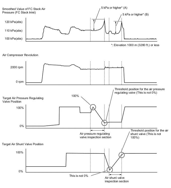
Result Result Proceed to Variation (B) of the "Smoothed Value of FC Stack Air Pressure (FC Stack Inlet)" value in the air shunt valve inspection section is less than 5 kPa (elevation 1000 m (3280 ft.) or less)*1 A Variation (A) of the "Smoothed Value of FC Stack Air Pressure (FC Stack Inlet)" value in the air pressure regulating valve inspection section is less than 5 kPa (elevation 1000 m (3280 ft.) or less)*2 B Other than above C
-
*1: The air shunt valve is malfunctioning
-
*2: The air pressure regulating valve is malfunctioning
-
-
Turn the power switch off.
A
REPLACE FC STACK ASSEMBLY Click here
B
REPLACE FC STACK ASSEMBLY Click here
C
-
-
CLEAR DTC
-
Connect the GTS to the DLC3.
-
Turn the power switch on (IG).
-
Turn the GTS on.
-
Enter the following menus: Powertrain / FC / Trouble Codes.
-
Clear the DTCs.
Powertrain > FC > Clear DTCs -
Turn the power switch off and wait for 3 minutes or more.
Result Proceed to NEXT
NEXT
-
-
SIMULATION TEST
-
Connect the GTS to the DLC3.
-
Turn the power switch on (READY).
-
Turn the GTS on.
-
Drive the vehicle for 10 minutes according to the freeze frame data (Vehicle Speed, Accelerator Degree, etc.).
If vehicle speeds, accelerator pedal positions, road conditions, ambient temperatures and climates at the time the malfunction occurred can be determined, take them into account.
Since malfunction detection is performed when a high load is applied, drive the vehicle under high load conditions, such as driving uphill. It is important that the vehicle speed is close to a speed recorded in the freeze frame data as much as possible. The "Smoothed Value of FC Stack Air Pressure (FC Stack Inlet)" is roughly less than 130 kPa(abs) during light load operation including idling.
CAUTION:
Perform this road test only in an appropriate safe location, in accordance with all local laws.
-
Enter the following menus: Powertrain / FC / Trouble Codes.
-
Check for DTCs.
Powertrain > FC > Trouble CodesResult Result Proceed to DTCs are not output A DTC P1DC5-450 is output* B
-
*: The air pressure regulating valve is malfunctioning
-
-
Turn the power switch off.
A
CHECK FOR INTERMITTENT PROBLEMS Click here
B
REPLACE FC STACK ASSEMBLY Click here
-