FC CONTROL SYSTEM, Diagnostic DTC:P1DC1-450
| DTC Code | DTC Name |
|---|---|
| P1DC1-450 | Low-range Hydrogen Pressure Too High |
DESCRIPTION
The hydrogen system of the FC system feeds the FC stack with hydrogen, so that the FC stack can generate power. The low-range pressure circuit is located after the hydrogen injectors, and pressure applied to the circuit is regulated by the hydrogen injectors to an appropriate level for FC stack power generation.
If the regulated low-range hydrogen pressure exceeds a threshold, the FC control ECU interprets it as a higher pressure limit error, and sets this DTC.
For the circuit diagram, refer to DTC P1DC0-450.
| DTC No. | Detection Item | DTC Detection Condition | Trouble Area | Warning Indicate |
|---|---|---|---|---|
| P1DC1-450 | Low-range Hydrogen Pressure Too High | Low-range hydrogen pressure has exceeded a threshold. This malfunction detection is active all the time. (1 trip detection logic) |
FC stack assembly (hydrogen injector, low-range hydrogen pressure sensor) | Master Warning Light: Comes on |
Tech Tips
If low-range hydrogen pressure increases despite hydrogen injectors being not forced to open, it is suspected that hydrogen injectors are malfunctioning.
| Vehicle Condition | FC shutdown (power switch on (IG)) |
FC startup process | FC intermittent operation | FC is generating power (vehicle is in stationary) |
FC is generating power (vehicle is traveling) |
FC shutdown process |
|---|---|---|---|---|---|---|
| Data List "FC Mode" |
FC Shutdown | FC Startup Process | FC Working | FC Shutdown Process | ||
| Data List "FC Intermittent Operation" |
OFF | ON | OFF | OFF | ||
| DTC Detection | ○ | ○ | ○ | ○ | ○ | ○ |
| DTC No. | Data List |
|---|---|
| P1DC1-450 |
|
The following items can be helpful when performing repairs:
-
Tank Shut Valve 1 Driving Request
-
Tank Shut Valve 2 Driving Request
-
Hydrogen Injector 1 Injection Request
-
Hydrogen Injector 2 Injection Request
-
Hydrogen Injector 3 Injection Request
-
Motor Room Side Hydrogen Detector Density
-
Tank Side Hydrogen Detector Density
Data List
-
Vehicle Speed
-
Shift Sensor Shift Position
-
Accelerator Degree
-
Ready
-
FC Mode
-
FC Intermittent Operation
-
FC Voltage before Boosting
-
FC Current
-
Target Hydrogen Pump Revolution
-
Hydrogen Pump Revolution
-
Target FC Stack Air Pressure (FC Stack Inlet)
-
Smoothed Value of FC Stack Air Pressure (FC Stack Inlet)
-
Target Mass Air Flow Value
-
Mass Air Flow Value
-
Target Air Compressor Revolution
-
Air Compressor Revolution
-
Target FC Stack Coolant Temperature (FC Stack Outlet)
-
Smoothed Value of FC Stack Coolant Temperature (FC Stack Outlet)
-
Exhaust Drainage Valve Driving Request
Common Data List items for FC inspection
| DTC No. | Active Test |
|---|---|
| P1DC1-450 | Hydrogen Injector |
Note
If any one of the hydrogen injectors does not close, malfunctioning injectors cannot be identified through an Active Test.
CAUTION / NOTICE / HINT
CAUTION:
-
Work procedures must be performed in an area with good ventilation (airflow) where hydrogen gas will not accumulate, and flames or other things that could act as ignition sources must not be present.
-
Accumulated hydrogen gas could ignite, resulting in a serious accident.
Note
When the vehicle is parked with the power switch off, if the FC control ECU judges that the FC stack temperature will go below 0°C (32°F), it activates the FC air compressor, hydrogen pump and FC cooling water pump for a maximum of 180 seconds and drains water from the FC stack assembly. When performing inspection or repairs with the power switch off (not on (IG) or on (READY)), disconnect the cable from the negative (-) auxiliary battery terminal before performing work (If the auxiliary battery voltage is needed to conduct inspection, warm up the FC system beforehand).
Tech Tips
After the repair, clear the DTCs and perform the following procedure to check that DTCs are not output.
-
Turn the power switch on (READY) with the shift lever in P, and check the Data List that "FC Mode" is FC Working and "FC Intermittent Operation" is OFF. Then, wait 2 minutes or more.
-
Check that the "Smoothed Value of Low-range Hydrogen Pressure" in the Data List is 280 kPa(abs) or less.
-
After completion of repair, check that no hydrogen leaks from the hydrogen system components with a hydrogen gas detector.
PROCEDURE
-
CHECK DTC OUTPUT
Note
The freeze frame data is cleared when DTCs are cleared. Be sure to make a note of necessary data in advance.
-
Connect the GTS to the DLC3.
-
Turn the power switch on (IG).
-
Turn the GTS on.
-
Enter the following menus: Powertrain / FC / Trouble Codes.
-
Check for DTCs.
Powertrain > FC > Trouble CodesResult Result Proceed to No DTCs are output, or DTCs except the ones in the table below are also output. A Any of the following DTCs are also output. B Malfunction Content Relevant DTC Sensor and Actuator Circuit Malfunction P1D9C-450 Hydrogen Injector No. 1 Circuit Low P1D9D-450 Hydrogen Injector No. 1 Circuit High P1DA2-450 Hydrogen Injector No. 2 Circuit Low P1DA3-450 Hydrogen Injector No. 2 Circuit High P1DA7-450 Hydrogen Injector No. 3 Circuit Low P1DA8-450 Hydrogen Injector No. 3 Circuit High P1DBC-450 Low-range Hydrogen Pressure Sensor Circuit Low P1DBD-450 Low-range Hydrogen Pressure Sensor Circuit High Tech Tips
-
DTC P1DC1-450 may be set due to problems that cause the DTCs shown above to be output. If such happens, troubleshoot the suspected area(s) corresponding to the output DTC(s) in order starting with the listed DTCs shown in the table above.
-
If DTC P1E40-450 or P1E41-450 is output together with P1DC1-450, hydrogen may have leaked from the low-range hydrogen pressure components, or hydrogen may have been discharged by the low-range hydrogen pressure relief valve. After completion of repair, check for hydrogen leaks in the FC stack assembly.
-
-
Turn the power switch off.
B 
GO TO DTC CHART Click here
A 
-
-
CLEAR DTC
-
Connect the GTS to the DLC3.
-
Turn the power switch on (IG).
-
Turn the GTS on.
-
Enter the following menus: Powertrain / FC / Trouble Codes.
-
Clear the DTCs.
Powertrain > FC > Clear DTCs -
Turn the power switch off and wait for 3 minutes or more.
Result Proceed to NEXT
NEXT
-
-
READ VALUE USING GTS
-
Connect the GTS to the DLC3.
-
Turn the power switch on (IG).
-
Turn the GTS on.
-
Enter the following menus: Powertrain / FC / Data List / FC Mode, Hydrogen Injector 1 Injection Request, Hydrogen Injector 2 Injection Request, Hydrogen Injector 3 Injection Request, Tank Shut Valve 1 Driving Request, Tank Shut Valve 2 Driving Request, Smoothed Value of Low-range Hydrogen Pressure
Powertrain > FC > Data ListTester Display FC Mode Hydrogen Injector 1 Injection Request Hydrogen Injector 2 Injection Request Hydrogen Injector 3 Injection Request Tank Shut Valve 1 Driving Request Tank Shut Valve 2 Driving Request Smoothed Value of Low-range Hydrogen Pressure -
Using the GTS snapshot, record the values of the Data List items listed above.
-
Turn the power switch on (READY) and check the Data List that "FC Mode" is FC Working.
Tech Tips
If DTCs are set and FC Working is disabled, record data from when the power switch is turned on (IG) until the FC system shuts down.
-
Check the "Smoothed Value of Low-range Hydrogen Pressure" with the following conditions met.
-
FC Mode = FC Startup Process*
-
Tank Shut Valve 1 Driving Request = ON
-
Tank Shut Valve 2 Driving Request = ON
-
Hydrogen Injector 1 Injection Request = OFF
-
Hydrogen Injector 2 Injection Request = OFF
-
Hydrogen Injector 3 Injection Request = OFF
*: If the FC system can be activated, check the Data List value with the "FC Mode" in FC Working.
Figure 1. Reference example
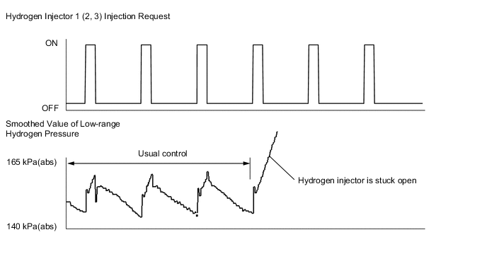
Result Result Proceed to "Smoothed Value of Low-range Hydrogen Pressure" increases when the "Hydrogen Injector Injection Request" in the Data List is OFF.* A Other than above B
-
*: The hydrogen injector is malfunctioning
-
-
Turn the power switch off.
A
REPLACE FC STACK ASSEMBLY Click here
B
CHECK FOR INTERMITTENT PROBLEMS Click here
-