FC CONTROL SYSTEM, Diagnostic DTC:P1DB1-450
| DTC Code | DTC Name |
|---|---|
| P1DB1-450 | High-range Hydrogen Pressure Sensor Correlation |
DESCRIPTION
The hydrogen system of the FC system feeds the FC stack with hydrogen, so that the FC stack can generate power. The hydrogen tank pressure sensor measures hydrogen pressure in the high-range pressure area including the hydrogen tank, and it transmits measured values to the meter as the remaining amount of hydrogen.
When the tank is filled at a hydrogen station, a hydrogen tank pressure sensor (for inlet side) value that is output just after completion of hydrogen filling is stored in the memory. If a pressure value, which is measured by the hydrogen tank pressure sensor (for outlet side) when the tank shut valves open, has deviated from the stored inlet pressure sensor value by more than a specified degree, the FC control ECU will interpret it as characteristic abnormality, and set this DTC.
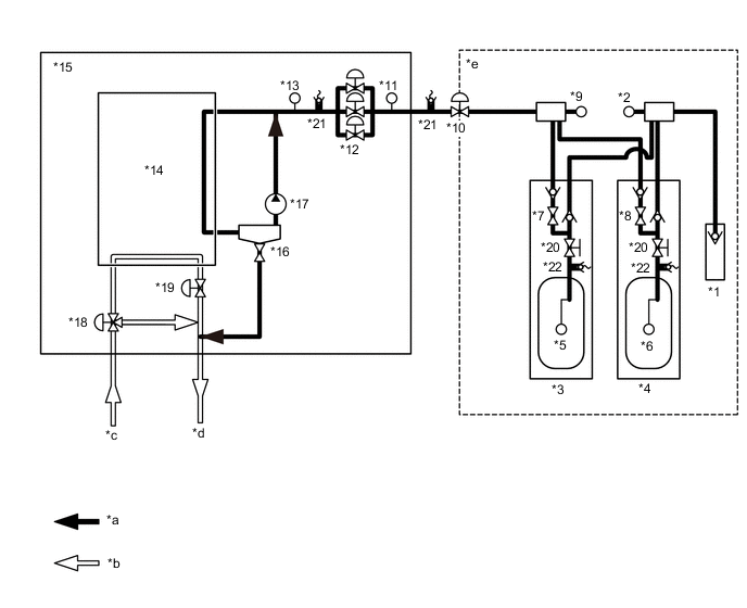
| *1 | Hydrogen Inlet Receptacle Assembly | *2 | Hydrogen Tank Pressure Sensor (for Inlet Side) |
| *3 | No. 1 Hydrogen Tank Assembly | *4 | No. 2 Hydrogen Tank Assembly |
| *5 | Hydrogen Tank Temperature Sensor 1 | *6 | Hydrogen Tank Temperature Sensor 2 |
| *7 | Tank Shut Valve 1 | *8 | Tank Shut Valve 2 |
| *9 | Hydrogen Tank Pressure Sensor (for Outlet Side) | *10 | Hydrogen Supply Regulator Assembly |
| *11 | Medium-range Hydrogen Pressure Sensor | *12 | Hydrogen Injector |
| *13 | Low-range Hydrogen Pressure Sensor | *14 | FC Stack |
| *15 | FC Stack Assembly | *16 | Exhaust Drainage Valve |
| *17 | Hydrogen Pump | *18 | Air Shunt Valve |
| *19 | Air Pressure Regulating Valve | *20 | Manual Valve |
| *21 | Pressure Relief Valve | *22 | Pressure Relief Device |
| *a | Hydrogen system | *b | Air system |
| *c | From the FC Air Compressor with Motor Assembly | *d | To the exhaust drainage pipe |
| *e | High-range Pressure Area | - | - |
| DTC No. | Detection Item | DTC Detection Condition | Trouble Area | Warning Indicate |
|---|---|---|---|---|
| P1DB1-450 | High-range Hydrogen Pressure Sensor Correlation | Following diagnostic checks are conducted when the power switch is turned on (READY) the first time after filling at a hydrogen station. If the difference between the following 2 pressure values is above a threshold, it is interpreted that a hydrogen tank pressure sensor is malfunctioning:
(3 trip detection logic)*1 |
|
Master Warning Light: Comes on |
-
*1: Filling hydrogen and then turning the power switch on (READY) is counted as 1 trip.
| Vehicle Condition | FC shutdown (power switch on (IG)) |
FC startup process | FC intermittent operation | FC is generating power (vehicle is in stationary) |
FC is generating power (vehicle is traveling) |
FC shutdown process |
|---|---|---|---|---|---|---|
| Data List "FC Mode" |
FC Shutdown | FC Startup Process | FC Working | FC Shutdown Process | ||
| Data List "FC Intermittent Operation" |
OFF | ON | OFF | OFF | ||
| DTC Detection | - | ○ | - | - | - | - |
Tech Tips
By accessing the "FC Mode" in the freeze frame data, the FC system condition at the time the malfunction occurred can be checked.
| DTC No. | Data List |
|---|---|
| P1DB1-450 |
|
The following items can be helpful when performing repairs:
-
Tank Shut Valve 1 Driving Request
-
Tank Shut Valve 2 Driving Request
-
Smoothed Value of Hydrogen Tank 1 Temperature
-
Smoothed Value of Hydrogen Tank 2 Temperature
Data List
-
Vehicle Speed
-
Shift Sensor Shift Position
-
Accelerator Degree
-
Ready
-
FC Mode
-
FC Intermittent Operation
-
FC Voltage before Boosting
-
FC Current
-
Target Low-range Hydrogen Pressure
-
Smoothed Value of Low-range Hydrogen Pressure
-
Target Hydrogen Pump Revolution
-
Hydrogen Pump Revolution
-
Target FC Stack Air Pressure (FC Stack Inlet)
-
Smoothed Value of FC Stack Air Pressure (FC Stack Inlet)
-
Target Mass Air Flow Value
-
Mass Air Flow Value
-
Target Air Compressor Revolution
-
Air Compressor Revolution
-
Target FC Stack Coolant Temperature (FC Stack Outlet)
-
Smoothed Value of FC Stack Coolant Temperature (FC Stack Outlet)
-
Exhaust Drainage Valve Driving Request
Common Data List items for FC inspection
WIRING DIAGRAM
CAUTION / NOTICE / HINT
Note
When the vehicle is parked with the power switch off, if the FC control ECU judges that the FC stack temperature will go below 0°C (32°F), it activates the FC air compressor, hydrogen pump and FC cooling water pump for a maximum of 180 seconds and drains water from the FC stack assembly. When performing inspection or repairs with the power switch off (not on (IG) or on (READY)), disconnect the cable from the negative (-) auxiliary battery terminal before performing work (If the auxiliary battery voltage is needed to conduct inspection, warm up the FC system beforehand).
Tech Tips
After the repair, clear the DTCs and perform the following procedure to check that DTCs are not output.
Hydrogen filling has to be conducted 3 times, so do not fill the tank full at the 1st or 2nd filling.
-
Open the fuel lid, and fill the tank at a hydrogen station.
-
Close the fuel lid.
-
Turn the power switch on (READY) and wait for 1 minute or more.
Tech Tips
The "Smoothed Value of High-range Hydrogen Pressure" and "Hydrogen Filling System High Pressure" of the Data List will be almost the same values.
-
Turn the Power switch off and wait for 3 minutes or more.
-
Open the fuel lid, and fill the tank at a hydrogen station.
-
Close the fuel lid.
-
Turn the power switch on (READY) and wait for 1 minute or more.
-
Turn the Power switch off and wait for 3 minutes or more.
-
Open the fuel lid, and fill the tank at a hydrogen station.
-
Close the fuel lid.
-
Turn the power switch on (READY) and wait for 1 minute or more.
PROCEDURE
-
CHECK DTC OUTPUT
Note
The freeze frame data is cleared when DTCs are cleared. Be sure to make a note of necessary data in advance.
-
Connect the GTS to the DLC3.
-
Turn the power switch on (IG).
-
Turn the GTS on.
-
Enter the following menus: Powertrain / FC / Trouble Codes.
-
Check for DTCs.
Powertrain > FC > Trouble CodesResult Result Proceed to P1DB1-450 only is output, or DTCs except the ones in the table below are also output. A Any of the following DTCs are also output. B Malfunction Content Relevant DTC Sensor and Actuator Circuit Malfunction P1DFC-450 Hydrogen Filling System High Pressure Sensor Circuit Low P1DFD-450 Hydrogen Filling System High Pressure Sensor Circuit High P1E02-450 Tank Shut Valve1 Circuit Low P1E03-450 Tank Shut Valve1 Circuit High P1E12-450 Tank Shut Valve2 Circuit Low P1E13-450 Tank Shut Valve2 Circuit High P1E19-450 Infrared Transmitter Circuit System Malfunction P1DE6-450 Hydrogen Tank Temperature Sensor Correlation P1E36-450 Tank Shut Valve 1 Stuck Open or Close P1E38-450 Tank Shut Valve 2 Stuck Open or Close Tech Tips
DTC P1DB1-450 may be set due to problems that cause the DTCs shown above to be output. If such happens, troubleshoot the suspected area(s) corresponding to the output DTC(s) in order of the listed DTCs shown in the table above.
-
Turn the power switch off.
B 
GO TO DTC CHART Click here
A 
-
-
CLEAR DTC
-
Connect the GTS to the DLC3.
-
Turn the power switch on (IG).
-
Turn the GTS on.
-
Enter the following menus: Powertrain / FC / Trouble Codes.
-
Clear the DTCs.
Powertrain > FC > Clear DTCs -
Turn the power switch off and wait for 3 minutes or more.
Result Proceed to NEXT
NEXT
-
-
CHECK DTC OUTPUT (P1E19-450)
-
Turn the power switch off.
-
Connect the GTS to the DLC3.
-
Press the fuel lid opener switch to unlock the fuel lid.
-
Fully open the fuel lid by hand, and wait for 2 minutes.
-
With the fuel lid fully open, turn the power switch on (IG).
-
Turn the GTS on.
-
Enter the following menus: Powertrain / FC / Trouble Codes.
Powertrain > FC > Trouble CodesResult Result Proceed to DTCs are not output A DTC P1E19-450 is output B -
Turn the power switch off.
B
GO TO DTC CHART Click here
A
-
-
READ VALUE USING GTS (SMOOTHED VALUE OF HIGH-RANGE HYDROGEN PRESSURE, HYDROGEN FILLING SYSTEM HIGH PRESSURE)
-
Open the fuel lid.
-
Connect the GTS to the DLC3.
-
Turn the power switch on (IG).
-
Turn the GTS on.
-
Enter the following menus: Powertrain / FC / Data List / Smoothed Value of High-range Hydrogen Pressure, Hydrogen Filling System High Pressure
Powertrain > FC > Data ListTester Display Hydrogen Filling System High Pressure Smoothed Value of High-range Hydrogen Pressure -
Using the GTS snapshot, record the values of the Data List items listed above.
-
Fill the tank with hydrogen.
-
Check the recorded snapshot data.
Result Result Proceed to "Hydrogen Filling System High Pressure" value in the Data List does increase during filling A "Hydrogen Filling System High Pressure" value in the Data List does not increase during filling B Tech Tips
DTCs may be output. Clear them with the GTS.
-
Turn the power switch off.
B
REPLACE HYDROGEN TANK PRESSURE SENSOR (FOR INLET SIDE) Click here
A
-
-
REPLACE HYDROGEN TANK PRESSURE SENSOR (FOR INLET SIDE)
Result Proceed to NEXT
NEXT
REPLACE HYDROGEN TANK PRESSURE SENSOR (FOR OUTLET SIDE) Click here