FC CONTROL SYSTEM, Diagnostic DTC:P1DA7-450, P1DA8-450
| DTC Code | DTC Name |
|---|---|
| P1DA7-450 | Hydrogen Injector No.3 Circuit Low |
| P1DA8-450 | Hydrogen Injector No.3 Circuit High |
DESCRIPTION
Refer to DTC P1D9C-450.
| DTC No. | Detection Item | DTC Detection Condition | Trouble Area | Warning Indicate |
|---|---|---|---|---|
| P1DA7-450 | Hydrogen Injector No.3 Circuit Low | All of the following conditions are met, and there is an open in the No. 3 hydrogen injector circuit or a short to the GND circuit (DTC detection signal is small) for more than 3 seconds.
(1 trip detection logic) |
|
Master Warning Light: Comes on |
| P1DA8-450 | Hydrogen Injector No.3 Circuit High | All of the following conditions are met, and there is a short in the +B circuit of the hydrogen injector 3 circuit (large DTC detection signal voltage) for more than 3 seconds.
(1 trip detection logic) |
|
Master Warning Light: Comes on |
| Vehicle Condition | FC shutdown (power switch on (IG)) |
FC startup process | FC intermittent operation | FC is generating power (vehicle is in stationary) |
FC is generating power (vehicle is traveling) |
FC shutdown process |
|---|---|---|---|---|---|---|
| Data List "FC Mode" |
FC Shutdown | FC Startup Process | FC Working | FC Shutdown Process | ||
| Data List "FC Intermittent Operation" |
OFF | ON | OFF | OFF | ||
| DTC Detection | ○ | ○ | ○ | ○ | ○ | - |
| DTC No. | Data List |
|---|---|
| P1DA7-450 | - |
| P1DA8-450 |
Tech Tips
It is suspected that malfunctions, or open/short circuits have occurred in the No. 3 hydrogen injector.
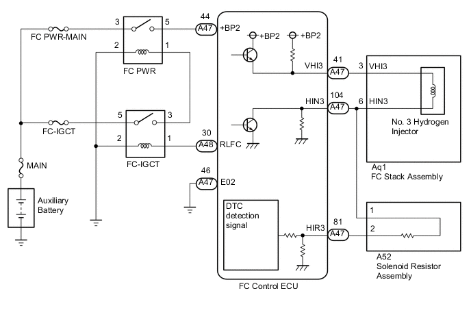
WIRING DIAGRAM
CAUTION / NOTICE / HINT
CAUTION:
-


Before the following operations are conducted, take precautions to prevent electric shock by turning the power switch off, wearing insulated gloves, and removing the service plug grips from both FC stack assembly and EV battery.
-
Inspecting the high-voltage system
-
Disconnecting the low voltage connector of the inverter with converter assembly
-
Disconnecting the low voltage connector of the EV battery
-
Disconnecting the low voltage connector of the FC stack assembly
-
Disconnecting the low voltage connector of the FC converter assembly
-
Tech Tips
No removal order is specified for the service plug grips of the FC stack assembly and EV battery.
-

After removing the service plug grip from the EV battery, put it in your pocket to prevent other technicians from accidentally reconnecting it while you are working on the high-voltage system. After removing the service grip from the FC stack assembly, store it in a safe location and use the "HIGH-VOLTAGE, DO NOT TOUCH" sign to notify other technicians that you are working on the high-voltage system.
-

*a Without waiting for 10 minutes After removal of the service plug grips of both FC stack assembly and EV battery, wait for at least 10 minutes before touching the high-voltage connectors and terminals. After waiting for 10 minutes, check the voltage at the terminals in the inspection point in the inverter with converter assembly. The voltage should be 0 V before beginning work.
Tech Tips
At least 10 minutes are necessary to discharge the high-voltage capacitors inside the inverter with converter assembly and FC stack assembly.
Note
-
When reinstalling the service plug grip to the FC stack assembly or the EV battery, slide the lever of the service plug until the letters "UNLOCK" are completely hidden, and insert it firmly.
-
Inspect the fuses of circuits related to this system before performing the following procedure.
-
When the vehicle is parked with the power switch off, if the FC control ECU judges that the FC stack temperature will go below 0°C (32°F), it activates the FC air compressor, hydrogen pump and FC cooling water pump for a maximum of 180 seconds and drains water from the FC stack assembly. When performing inspection or repairs with the power switch off (not on (IG) or on (READY)), disconnect the cable from the negative (-) auxiliary battery terminal before performing work (If the auxiliary battery voltage is needed to conduct inspection, warm up the FC system beforehand).
Tech Tips
After the repair, clear the DTCs and perform the following procedure to check that DTCs are not output.
-
Turn the power switch on (IG) and wait for 3 seconds or more.
PROCEDURE
-
CHECK TERMINAL VOLTAGE (POWER SOURCE OF FC CONTROL ECU)
-
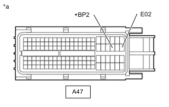
*a Front view of wire harness connector
(to FC Control ECU)
Disconnect the FC control ECU connector.
Note
Do not disconnect the A48 connector of the FC control ECU.
-
Turn the power switch on (IG).
-
Measure the voltage according to the value(s) in the table below.
Standard Voltage Tester Connection Condition Specified Condition A47-44 (+BP2) - A47-46 (E02) Power switch on (IG) 11 to 14 V -
Turn the power switch off.
-
Reconnect the FC control ECU connector.
Result Proceed to OK NG
NG 
CHECK HARNESS AND CONNECTOR (FC CONTROL ECU - BODY GROUND) Click here
OK 
-
-
CHECK HARNESS AND CONNECTOR (FC CONTROL ECU - FC STACK ASSEMBLY (NO. 3 HYDROGEN INJECTOR) - SOLENOID RESISTOR ASSEMBLY)
CAUTION:
Be sure to wear insulated gloves.
-
Check that the service plug grip is not installed to FC stack assembly and EV battery.
Note
After removing the service plug grip, do not turn the power switch on (READY), unless instructed by the repair manual because this may cause a malfunction.
-
Disconnect the FC control ECU connector.
-
Disconnect the FC stack assembly (No. 3 hydrogen injector) connector.
-
Disconnect the solenoid resistor assembly connector.
-
Measure the resistance according to the value(s) in the table below.
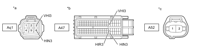
*a Front view of wire harness connector
(to FC Stack Assembly (No. 3 Hydrogen Injector))
*b Front view of wire harness connector
(to FC Control ECU)
*c Front view of wire harness connector
(to Solenoid Resistor Assembly)
- - Standard Resistance Tester Connection Condition Specified Condition A47-41 (VHI3) - Aq1-3 (VHI3) Always Below 1 Ω A47-104 (HIN3) or Aq1-6 (HIN3) - A52-1 Always Below 1 Ω A47-81 (HIR3) - A52-2 Always Below 1 Ω A47-41 (VHI3) or Aq1-3 (VHI3) - Body ground and other terminals Always 10 kΩ or higher A47-104 (HIN3), Aq1-6 (HIN3) or A52-1 - Body ground and other terminals Always 10 kΩ or higher A47-81 (HIR3) or A52-2 - Body ground and other terminals Always 10 kΩ or higher -
Connect the cable to the negative (-) auxiliary battery terminal.
-
Turn the power switch on (IG).
-
Measure the voltage according to the value(s) in the table below.
Standard Voltage Tester Connection Condition Specified Condition A47-41 (VHI3), A47-104 (HIN3) or A47-81 (HIR3) - Body ground Power switch on (IG) Below 1 V -
Turn the power switch off.
-
Disconnect the cable from the negative (-) auxiliary battery terminal.
-
Reconnect the solenoid resistor assembly connector.
-
Reconnect the FC stack assembly (No. 3 hydrogen injector) connector.
-
Reconnect the FC control ECU connector.
Result Proceed to OK NG
NG 
REPAIR OR REPLACE HARNESS OR CONNECTOR
OK
-
-
CHECK FC STACK ASSEMBLY (NO. 3 HYDROGEN INJECTOR)
CAUTION:
Be sure to wear insulated gloves.
-
Check that the service plug grip is not installed to FC stack assembly and EV battery.
Note
After removing the service plug grip, do not turn the power switch on (READY), unless instructed by the repair manual because this may cause a malfunction.
-
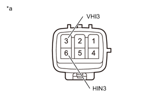
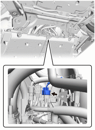
*a Component without harness connected
(FC Stack Assembly (No. 3 Hydrogen Injector))
Disconnect the Aq1 FC stack assembly (No. 3 hydrogen injector) connector.
-
Measure the resistance according to the value(s) in the table below.
Standard Resistance Tester Connection Condition Specified Condition 3 (VHI3) - 6 (HIN3) 20°C (68°F) 1.2 to 1.6 Ω 3 (VHI3) or 6 (HIN3) - Body ground and other terminals Always 10 kΩ or higher -
Reconnect the Aq1 FC stack assembly (No. 3 hydrogen injector) connector.
Result Proceed to OK NG
*
-
*: The No. 3 hydrogen injector is malfunctioning
-
NG
REPLACE FC STACK ASSEMBLY Click here
OK
-
-
INSPECT SOLENOID RESISTOR ASSEMBLY
-
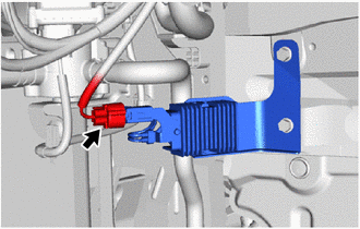
Disconnect the A52 solenoid resistor assembly connector.
-
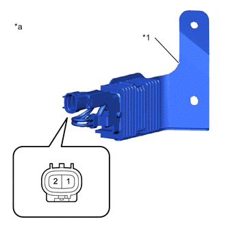
*1 Bracket *a Component without harness connected
(Solenoid Resistor Assembly)
Measure the resistance according to the value(s) in the table below.
Standard Resistance Tester Connection Condition Specified Condition 1 - 2 20°C (68°F) 5.04 to 5.57 Ω -
Using a megohmmeter set to 500 V, measure the resistance according to the value(s) in the table below.
CAUTION:
Be sure to wear insulated gloves.
Note
Be sure to set the megohmmeter to 500 V when performing this test. Using a setting higher than 500 V can result in damage to the component being inspected.
Standard Resistance Tester Connection Condition Specified Condition 1 - Bracket Always 100 MΩ or higher 2 - Bracket Always 100 MΩ or higher -
Reconnect the A52 solenoid resistor assembly connector.
Result Proceed to OK NG
OK
REPLACE FC CONTROL ECU Click here
NG
REPLACE SOLENOID RESISTOR ASSEMBLY Click here
-
-
CHECK HARNESS AND CONNECTOR (FC CONTROL ECU - BODY GROUND)
-
Disconnect the FC control ECU connector.
-
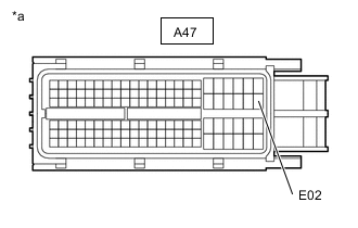
*a Front view of wire harness connector
(to FC Control ECU)
Measure the resistance according to the value(s) in the table below.
Standard Resistance Tester Connection Condition Specified Condition A47-46 (E02) - Body ground Always Below 1 Ω -
Reconnect the FC control ECU connector.
Result Proceed to OK NG
NG
REPAIR OR REPLACE HARNESS OR CONNECTOR
OK
-
-
CHECK TERMINAL VOLTAGE (POWER SOURCE OF FC PWR RELAY)
-

*1 Motor Compartment Relay Block *2 FC PWR Relay Holder Remove the FC PWR relay from the motor compartment relay block.
-
Turn the power switch on (IG).
-
Measure the voltage according to the value(s) in the table below.
Standard Voltage Tester Connection Condition Specified Condition 1 (FC PWR relay holder) - Body ground Power switch on (IG) 11 to 14 V -
Turn the power switch off.
-
Reinstall the FC PWR relay.
Result Proceed to OK NG
NG
CHECK HARNESS AND CONNECTOR (FC-IGCT RELAY - FC PWR RELAY) Click here
OK
-
-
INSPECT RELAY (FC PWR)
Result Proceed to OK NG
NG
REPLACE RELAY (FC PWR)
OK
-
CHECK TERMINAL VOLTAGE (POWER SOURCE OF FC PWR RELAY)
-
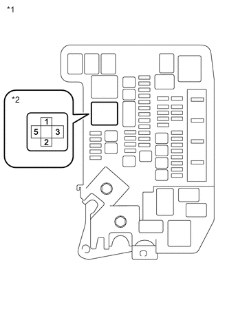
*1 Motor Compartment Relay Block *2 FC PWR Relay Holder Remove the FC PWR relay from the motor compartment relay block.
-
Measure the voltage according to the value(s) in the table below.
Standard Voltage Tester Connection Condition Specified Condition 3 (FC PWR relay holder) - Body ground Power switch off 11 to 14 V -
Reinstall the FC PWR relay.
Result Proceed to OK NG
NG
REPAIR OR REPLACE HARNESS OR CONNECTOR (FC PWR RELAY - AUXILIARY BATTERY)
OK
-
-
CHECK HARNESS AND CONNECTOR (FC PWR RELAY - BODY GROUND)
-
Remove the FC PWR relay from the motor compartment relay block.
-

*1 Motor Compartment Relay Block *2 FC PWR Relay Holder Measure the resistance according to the value(s) in the table below.
Standard Resistance Tester Connection Condition Specified Condition 2 (FC PWR relay holder) - Body ground Always Below 1 Ω -
Reinstall the FC PWR relay.
Result Proceed to OK NG
NG
REPAIR OR REPLACE HARNESS OR CONNECTOR
OK
-
-
CHECK HARNESS AND CONNECTOR (FC CONTROL ECU - FC PWR RELAY)
-
Disconnect the FC control ECU connector.
-
Remove the FC PWR relay from the motor compartment relay block.
-
Measure the resistance according to the value(s) in the table below.
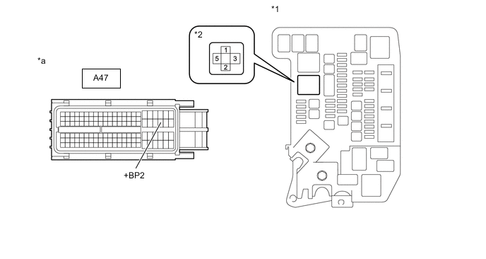
*1 Motor Compartment Relay Block *2 FC PWR Relay Holder *a Front view of wire harness connector
(to FC Control ECU)
- - Standard Resistance Tester Connection Condition Specified Condition A47-44 (+BP2) - 5 (FC PWR relay holder) Always Below 1 Ω A47-44 (+BP2) or 5 (FC PWR relay holder) - Body ground and other terminals Always 10 kΩ or higher -
Reinstall the FC PWR relay.
-
Reconnect the FC control ECU connector.
Result Proceed to OK NG
OK
CHECK FOR INTERMITTENT PROBLEMS Click here
NG
REPAIR OR REPLACE HARNESS OR CONNECTOR
-
-
CHECK HARNESS AND CONNECTOR (FC-IGCT RELAY - FC PWR RELAY)
-
Remove the FC-IGCT relay from the motor compartment relay block.
-
Remove the FC PWR relay from the motor compartment relay block.
-
Measure the resistance according to the value(s) in the table below.
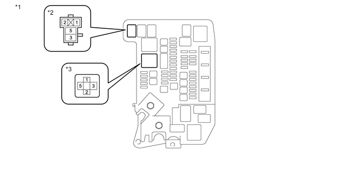
*1 Motor Compartment Relay Block *2 FC-IGCT Relay Holder *3 FC PWR Relay Holder - - Standard Resistance Tester Connection Condition Specified Condition 3 (FC-IGCT relay holder) - 1 (FC PWR relay holder) Always Below 1 Ω 3 (FC-IGCT relay holder) or 1 (FC PWR relay holder) - Body ground and other terminals Always 10 kΩ or higher -
Reinstall the FC PWR relay.
-
Reinstall the FC-IGCT relay.
Result Proceed to OK NG
OK
CHECK FOR INTERMITTENT PROBLEMS Click here
NG
REPAIR OR REPLACE HARNESS OR CONNECTOR
-