FC CONTROL SYSTEM, Diagnostic DTC:P1DCC-450, P1DCD-450
| DTC Code | DTC Name |
|---|---|
| P1DCC-450 | Motor Room Side Hydrogen Detector Circuit Low |
| P1DCD-450 | Motor Room Side Hydrogen Detector Circuit High |
DESCRIPTION
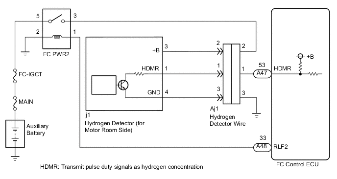
2 hydrogen detectors are used to detect hydrogen leaks from the vehicle pipe fittings etc., and they transmit signals as hydrogen concentration to the FC control ECU. One of the 2 detectors is mounted on the bottom surface of the cowl top panel of the motor compartment, and the other is provided between the hydrogen tank assemblies located at the under floor.
Concentration detection begins when approximately 5 seconds have elapsed after the power switch is turned from off to on (IG). When a detected concentration is above 2%, a warning light is illuminated to indicate it to the driver, and when it is above 3%, the FC system is forced to shut down.
The sensor actuation circuit has the bridge circuit shown in the illustration below, and the detection and compensation elements are designed to be equal in resistance when they are exposed to air without hydrogen gas. As a result, RS x R1 = RR x R2 is maintained, and the bridge circuit is in equilibrium, causing a sensor output to be 0 V. However, if the detection element is exposed to air that includes hydrogen gas, it burns and the resistance will increase due to the heat, causing the bridge circuit to become unbalanced, as a result, the sensor output will also increase. This sensor output is proportional to the concentration of hydrogen gas.
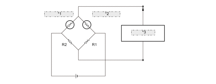
| *1 | Detection element RS |
| *2 | Compensation element RR |
| *3 | Sensor output |
| DTC No. | Detection Item | DTC Detection Condition | Trouble Area | Warning Indicate |
|---|---|---|---|---|
| P1DCC-450 | Motor Room Side Hydrogen Detector Circuit Low | FC PWR2 relay is ON and the hydrogen detector (for motor compartment) voltage has remained at less than 0.3 V for 3 seconds. (1 trip detection logic) |
|
Master Warning Light: Comes on |
| P1DCD-450 | Motor Room Side Hydrogen Detector Circuit High | FC PWR2 relay is ON and the hydrogen detector (for motor compartment) voltage has remained at more than 4.65 V for 3 seconds. (1 trip detection logic) |
|
Master Warning Light: Comes on |
| Vehicle Condition | FC shutdown (power switch on (IG)) |
FC startup process | FC intermittent operation | FC is generating power (vehicle is in stationary) |
FC is generating power (vehicle is traveling) |
FC shutdown process |
|---|---|---|---|---|---|---|
| Data List "FC Mode" |
FC Shutdown | FC Startup Process | FC Working | FC Shutdown Process | ||
| Data List "FC Intermittent Operation" |
OFF | ON | OFF | OFF | ||
| DTC Detection | ○ | ○ | ○ | ○ | ○ | - |
| DTC No. | Data List |
|---|---|
| P1DCC-450 | Motor Room Side Hydrogen Detector Voltage |
| P1DCD-450 |
WIRING DIAGRAM
CAUTION / NOTICE / HINT
Note
-
Inspect the fuses of circuits related to this system before performing the following procedure.
-
When the vehicle is parked with the power switch off, if the FC control ECU judges that the FC stack temperature will go below 0°C (32°F), it activates the FC air compressor, hydrogen pump and FC cooling water pump for a maximum of 180 seconds and drains water from the FC stack assembly. When performing inspection or repairs with the power switch off (not on (IG) or on (READY)), disconnect the cable from the negative (-) auxiliary battery terminal before performing work. (If the auxiliary battery voltage is needed to conduct inspection, warm up the FC system beforehand)
Tech Tips
After the repair, clear the DTCs and perform the following procedure to check that DTCs are not output.
-
Turn the power switch on (IG) and wait for 30 seconds or more.
PROCEDURE
-
CHECK DTC OUTPUT
-
Connect the GTS to the DLC3.
-
Turn the power switch on (IG).
-
Turn the GTS on.
-
Enter the following menus: Powertrain / FC / Trouble Codes.
-
Check for DTCs.
Powertrain > FC > Trouble CodesResult Result Proceed to Any of the following DTCs are also output. A P1DCC-450 or P1DCD-450 only is output, or DTCs except the ones in the table below are also output. B Malfunction Content Relevant DTC Sensor and Actuator Circuit Malfunction P0100-450 Mass Air Flow Circuit P1DD2-450 Tank Side Hydrogen Detector Circuit Low P1DD3-450 Tank Side Hydrogen Detector Circuit High Communication System Malfunction U1162-450 Lost Communication with Hydrogen Filling System -
Turn the power switch off.
B 
GO TO STEP 6 Click here
A 
-
-
CHECK TERMINAL VOLTAGE (POWER SOURCE OF FC PWR2 RELAY)
-
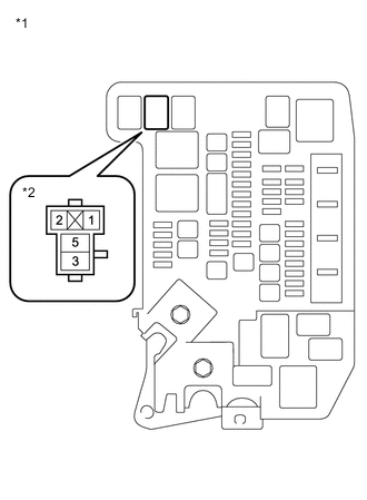
*1 Motor Compartment Relay Block *2 FC PWR2 Relay Holder Remove the FC PWR2 relay from the motor compartment relay block.
-
Turn the power switch on (IG).
-
Measure the voltage according to the value(s) in the table below.
Standard Voltage Tester Connection Condition Specified Condition 1 (FC PWR2 relay holder) - Body ground Power switch on (IG) 11 to 14 V -
Turn the power switch off.
-
Reinstall the FC PWR2 relay.
Result Proceed to OK NG
NG
CHECK HARNESS AND CONNECTOR (FC CONTROL ECU - FC PWR2 RELAY) Click here
OK
-
-
INSPECT RELAY (FC PWR2)
Result Proceed to OK NG
NG 
REPLACE RELAY (FC PWR2)
OK
-
CHECK HARNESS AND CONNECTOR (FC PWR2 RELAY - BODY GROUND)
-
*1 Motor Compartment Relay Block *2 FC PWR2 Relay Holder Remove the FC PWR2 relay from the motor compartment relay block.
-
Measure the resistance according to the value(s) in the table below.
Standard Resistance Tester Connection Condition Specified Condition 2 (FC PWR2 relay holder) - Body ground Always Below 1 Ω -
Reinstall the FC PWR2 relay.
Result Proceed to OK NG
NG
REPAIR OR REPLACE HARNESS OR CONNECTOR
OK
-
-
CHECK TERMINAL VOLTAGE (POWER SOURCE OF FC PWR2 RELAY)
-
*1 Motor Compartment Relay Block *2 FC PWR2 Relay Holder Remove the FC PWR2 relay from the motor compartment relay block.
-
Measure the voltage according to the value(s) in the table below.
Standard Voltage Tester Connection Condition Specified Condition 5 (FC PWR2 relay holder) - Body ground Power switch off 11 to 14 V -
Reinstall the FC PWR2 relay.
Result Proceed to OK NG
NG
REPAIR OR REPLACE HARNESS OR CONNECTOR (FC PWR2 RELAY - AUXILIARY BATTERY)
OK
-
-
CHECK TERMINAL VOLTAGE (POWER SOURCE OF HYDROGEN DETECTOR (FOR MOTOR ROOM SIDE))
-
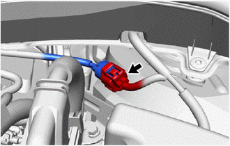
Disconnect the hydrogen detector (for motor room side) connector.
-
Turn the power switch on (IG).
-
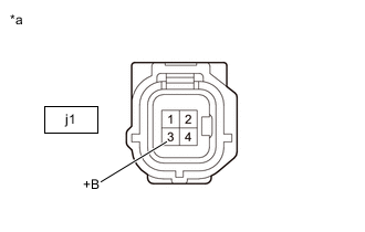
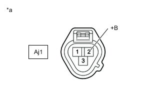
*a Front view of wire harness connector
(to Hydrogen Detector (for Motor Room Side))
Measure the voltage according to the value(s) in the table below.
Standard Voltage Tester Connection Condition Specified Condition j1-3 (+B) - Body ground Power switch on (IG) 11 to 14 V -
Turn the power switch off.
-
Reconnect the hydrogen detector (for motor room side) connector.
Result Proceed to OK NG
NG
CHECK TERMINAL VOLTAGE (POWER SOURCE OF HYDROGEN DETECTOR (FOR MOTOR ROOM SIDE)) Click here
OK
-
-
CHECK HARNESS AND CONNECTOR (HYDROGEN DETECTOR (FOR MOTOR ROOM SIDE) - BODY GROUND)
-
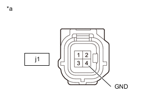
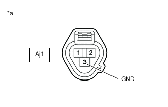
*a Front view of wire harness connector
(to Hydrogen Detector (for Motor Room Side))
Disconnect the hydrogen detector (for motor room side) connector.
-
Measure the resistance according to the value(s) in the table below.
Standard Resistance Tester Connection Condition Specified Condition j1-4 (GND) - Body ground Always Below 1 Ω -
Reconnect the hydrogen detector (for motor room side) connector.
Result Proceed to OK NG
NG
CHECK HARNESS AND CONNECTOR (HYDROGEN DETECTOR WIRE - BODY GROUND) Click here
OK
-
-
CHECK HARNESS AND CONNECTOR (FC CONTROL ECU - HYDROGEN DETECTOR (FOR MOTOR ROOM SIDE))
-
Disconnect the FC control ECU connector.
-
Disconnect the Hydrogen Detector (for Motor Room Side) connector.
-
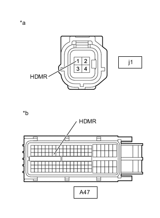
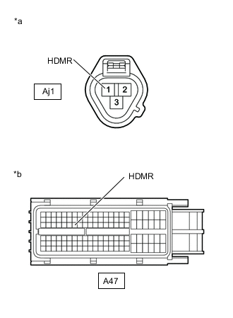
*a Front view of wire harness connector
(to Hydrogen Detector (for Motor Room Side))
*b Front view of wire harness connector
(to FC Control ECU)
Measure the resistance according to the value(s) in the table below.
Standard Resistance Tester Connection Condition Specified Condition A47-53 (HDMR) - j1-1 (HDMR) Always Below 1 Ω A47-53 (HDMR) or j1-1 (HDMR) - Body ground and other terminals Always 10 kΩ or higher -
Reconnect the Hydrogen Detector (for Motor Room Side) connector.
-
Reconnect the FC control ECU connector.
Result Proceed to OK NG
NG
CHECK HARNESS AND CONNECTOR (FC CONTROL ECU - HYDROGEN DETECTOR WIRE) Click here
OK
-
-
REPLACE HYDROGEN DETECTOR (FOR MOTOR ROOM SIDE)
Result Proceed to NEXT
NEXT
-
CLEAR DTC
-
Connect the GTS to the DLC3.
-
Turn the power switch on (IG).
-
Turn the GTS on.
-
Enter the following menus: Powertrain / FC / Trouble Codes.
-
Clear the DTCs.
Powertrain > FC > Clear DTCs -
Turn the Power switch off and wait for 3 minutes or more.
Result Proceed to NEXT
NEXT
-
-
CHECK DTC OUTPUT
-
Connect the GTS to the DLC3.
-
Turn the power switch on (IG) and wait for 30 seconds or more.
-
Turn the GTS on.
-
Enter the following menus: Powertrain / FC / Trouble Codes.
-
Check for DTCs.
Powertrain > FC > Trouble CodesResult Result Proceed to DTC P1DCC-450 or P1DCD-450 are output A DTCs are not output B -
Turn the power switch off.
A
REPLACE FC CONTROL ECU Click here
B
END
-
-
CHECK HARNESS AND CONNECTOR (FC CONTROL ECU - HYDROGEN DETECTOR WIRE)
-
Disconnect the FC control ECU connector.
-
Disconnect the hydrogen detector wire connector.
-
*a Front view of wire harness connector
(to Hydrogen Detector Wire)
*b Front view of wire harness connector
(to FC Control ECU)
Measure the resistance according to the value(s) in the table below.
Standard Resistance Tester Connection Condition Specified Condition A47-53 (HDMR) - Aj1-1 (HDMR) Always Below 1 Ω A47-53 (HDMR) or Aj1-1 (HDMR) - Body ground and other terminals Always 10 kΩ or higher -
Reconnect the hydrogen detector wire connector.
-
Reconnect the FC control ECU connector.
Result Proceed to OK NG
OK
REPLACE HYDROGEN DETECTOR WIRE Click here
NG
REPAIR OR REPLACE HARNESS OR CONNECTOR
-
-
CHECK HARNESS AND CONNECTOR (HYDROGEN DETECTOR WIRE - BODY GROUND)
-
*a Front view of wire harness connector
(to Hydrogen Detector Wire)
Disconnect the hydrogen detector wire connector.
-
Measure the resistance according to the value(s) in the table below.
Standard Resistance Tester Connection Condition Specified Condition Aj1-3 (GND) - Body ground Always Below 1 Ω -
Reconnect the Aj1 hydrogen detector wire connector.
Result Proceed to OK NG
OK
REPLACE HYDROGEN DETECTOR WIRE Click here
NG
REPAIR OR REPLACE HARNESS OR CONNECTOR
-
-
CHECK TERMINAL VOLTAGE (POWER SOURCE OF HYDROGEN DETECTOR (FOR MOTOR ROOM SIDE))
-
Disconnect the hydrogen detector wire connector.
-
Turn the power switch on (IG).
-
*a Front view of wire harness connector
(to Hydrogen Detector Wire)
Measure the voltage according to the value(s) in the table below.
Standard Voltage Tester Connection Condition Specified Condition Aj1-2 (+B) - Body ground Power switch on (IG) 11 to 14 V -
Turn the power switch off.
-
Reconnect the Aj1 hydrogen detector wire connector.
Result Proceed to OK NG
OK
REPLACE HYDROGEN DETECTOR WIRE Click here
NG
REPAIR OR REPLACE HARNESS OR CONNECTOR (HYDROGEN DETECTOR WIRE - FC PWR2 RELAY HOLDER)
-
-
CHECK HARNESS AND CONNECTOR (FC CONTROL ECU - FC PWR2 RELAY)
-
Disconnect the FC control ECU connector.
-
Remove the FC PWR2 relay from the motor compartment relay block.
-
Measure the resistance according to the value(s) in the table below.
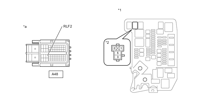
*1 Motor Compartment Relay Block *2 FC PWR2 Relay Holder *a Front view of wire harness connector
(to FC Control ECU)
- - Standard Resistance Tester Connection Condition Specified Condition A48-33 (RLF2) - 1 (FC PWR2 relay holder) Always Below 1 Ω A48-33 (RLF2) or 1 (FC PWR2 relay holder) - Body ground and other terminals Always 10 kΩ or higher -
Reinstall the FC PWR2 relay.
-
Reconnect the FC control ECU connector.
Result Proceed to OK NG
OK
REPLACE FC CONTROL ECU Click here
NG
REPAIR OR REPLACE HARNESS OR CONNECTOR
-