INVERTER WITH CONVERTER INSTALLATION
PROCEDURE
-
INSTALL HIGH VOLTAGE FUSE
CAUTION:
Wear insulated gloves.
Tech Tips
This procedure is performed when the high voltage fuse must be replaced with a new one.
-
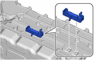
As shown in the illustration, set the inverter terminal sub-assembly onto the inverter with converter assembly.
Tech Tips
It is also acceptable to secure the inverter terminal sub-assembly using other tools, instead of setting it on the inverter with converter assembly.
-
Install the high voltage fuse to the inverter terminal sub-assembly with 2 new nuts.
- Torque:
- 4.2 N*m { 43 kgf*cm, 37 in.*lbf }
Note
Make sure to use a torque wrench to tighten.
-
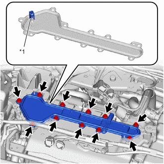
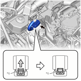
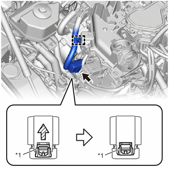
*1 Interlock Connector Remove the 11 bolts and inverter terminal cover from the inverter with converter assembly.
Note
-
The inverter terminal cover has an interlock connector, so pull it up perpendicularly.
-
Do not touch the rubber seal of the inverter terminal cover.
-
-
Using an insulated tool, install the inverter terminal sub-assembly to the inverter with converter assembly.
- Torque:
- 4.2 N*m { 43 kgf*cm, 37 in.*lbf }
Note
-
Be careful not to drop any nuts into the inverter with converter assembly.
-
Make sure to use a torque wrench to tighten.
-
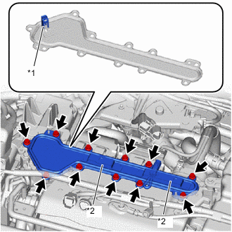
*1 Interlock Connector *2 Connector Bracket Temporarily install the inverter terminal cover with the 11 bolts to prevent any foreign matter or water from entering the inverter with converter assembly.
Note
-
Make sure that the rubber seal of the inverter terminal cover is securely installed and that no foreign matter is adhering to it, then install it.
-
Do not touch the rubber seal of the inverter terminal cover.
-
Do not install the inverter terminal cover while pressing down on the connector bracket.
-
Securely connect the interlock connector.
-
-
-
INSTALL FC CONVERTER CABLE INTER LOCK WIRE
-
Engage the clamp to install the FC converter cable inter lock wire to the inverter terminal cover.
-
-
INSTALL INVERTER COOLING INLET PIPE
-
To prevent contamination by foreign matter or water droplets, remove the plastic bags from the connecting portions of the No. 2 inverter cooling inlet hose and inverter with converter assembly immediately before performing the procedure.
-
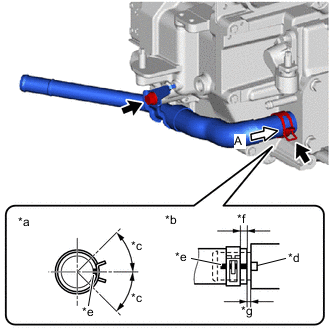
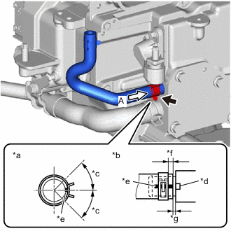
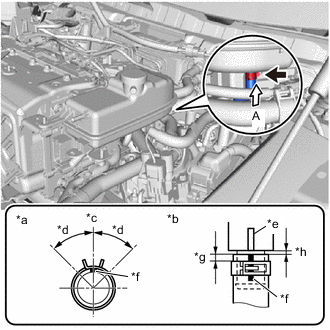
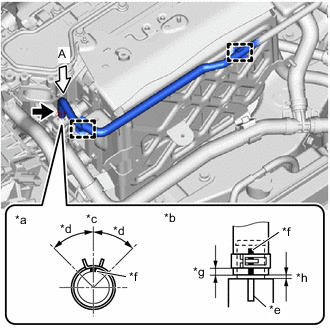
*a View A *b Hose end and hose clip location *c Claw area of hose clip: 45° *d Indentation of Inverter with Converter Assembly *e Hose paint mark (yellow) *f Distance from hose end to hose clip position: 2.0 to 5.0 mm (0.0787 to 0.1969 in.) *g Distance from hose end to stopper portion: 0 to 2 mm (0 to 0.0787 in.) mm Connect the No. 2 inverter cooling inlet hose to the inverter with converter assembly and slide the hose clip to secure it.
Note
Align the hose and the hose clip at the locations shown in the illustration and install them.
-
Install the inverter cooling inlet pipe to the inverter with converter assembly with the bolt.
- Torque:
- 10 N*m { 102 kgf*cm, 7 ft.*lbf }
-
-
INSTALL NO. 1 INVERTER DRAIN HOSE
-
To prevent contamination by foreign matter or water droplets, remove the plastic bags from the connecting portions of the No. 1 inverter drain hose and inverter with converter assembly immediately before performing the procedure.
-
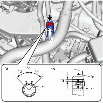
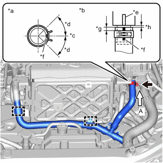
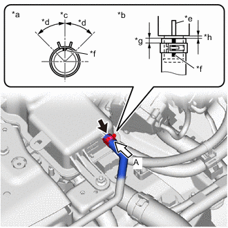
*a View A *b Hose end and hose clip location *c Claw area of hose clip: 45° *d Indentation of Inverter with Converter Assembly *e Hose paint mark (white) *f Distance from hose end to hose clip position: 2.0 to 5.0 mm (0.0787 to 0.1969 in.) *g Distance from hose end to stopper portion: 0 to 2 mm (0 to 0.0787 in.) mm Connect the No. 1 inverter drain hose to the inverter with converter assembly and slide the hose clip to secure it.
Note
Align the hose and the hose clip at the locations shown in the illustration and install them.
-
-
INSTALL INVERTER WITH CONVERTER ASSEMBLY
CAUTION:
Wear insulated gloves.
-
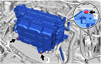
Temporarily install the inverter with converter assembly to the center frame crossmember sub-assembly with the bolt and 2 nuts.
Note
-
The inverter with converter assembly is very heavy, so when removing it from the vehicle, perform the work with 2 people and be careful not to damage any of the surrounding components.
-
When lifting up the inverter with converter assembly, to prevent damage, do not hold it by the water pipe, water hose or connector portion.
-
To prevent damage from static electricity, do not touch the connector terminal portion of the inverter with converter assembly.
-
-
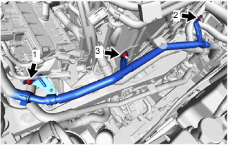
Fully tighten the bolt and 2 nuts in the sequence shown in the illustration.
- Torque:
- Bolt
- 23 N*m { 235 kgf*cm, 17 ft.*lbf }
- Nut
- 29 N*m { 296 kgf*cm, 21 ft.*lbf }
-
Connect the No. 2 motor compartment wire to the inverter with converter assembly with the nut.
- Torque:
- 18 N*m { 184 kgf*cm, 13 ft.*lbf }
-
Close the terminal cap cover.
-
-
INSTALL INVERTER PROTECTOR
-
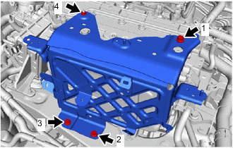
Temporarily install the inverter protector to the inverter with converter assembly and center frame crossmember sub-assembly with the 3 bolts and nut.
-
Fully tighten the 3 bolts and nut in the sequence shown in the illustration.
- Torque:
- Bolt
- 21 N*m { 214 kgf*cm, 15 ft.*lbf }
- Nut
- 10 N*m { 102 kgf*cm, 7 ft.*lbf }
-
-
CONNECT NO. 1 INVERTER COOLING INLET HOSE
-
To prevent contamination by foreign matter or water droplets, remove the plastic bags from the connecting portions of the No. 1 inverter cooling inlet hose and inverter cooling inlet pipe immediately before performing the procedure.
-
*a View A *b Hose end and hose clip location *c Top of vehicle *d Claw area of hose clip: 45° *e Pipe paint mark (yellow) *f Hose paint mark (yellow) *g Distance from hose end to hose clip position: 2.0 to 5.0 mm (0.0787 to 0.1969 in.) Connect the No. 1 inverter cooling inlet hose to the inverter cooling inlet pipe and slide the hose clip to secure it.
Note
Align the hose and the hose clip at the locations shown in the illustration and install them.
-
-
INSTALL INVERTER RESERVE TANK ASSEMBLY
-
To prevent contamination by foreign matter or water droplets, remove the plastic bags from the connecting portions of the No. 1 inverter drain hose and inverter reserve tank assembly immediately before performing the procedure.
-
*a View A *b Hose end and hose clip location *c Rear of vehicle *d Claw area of hose clip: 45° *e Inverter Reserve Tank Aassembly Rib *f Hose paint mark (yellow) *g Distance from hose end to hose clip position: 2.0 to 5.0 mm (0.0787 to 0.1969 in.) *h Distance from hose end to stopper portion: 0 to 2 mm (0 to 0.0787 in.) mm Connect the No. 1 inverter drain hose to the inverter reserve tank assembly and slide the hose clip to secure it.
Note
Align the hose and the hose clip at the locations shown in the illustration and install them.
-
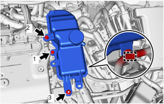
Temporarily install the inverter reserve tank assembly to the inverter with converter assembly with the 2 bolts and nut.
-
Fully tighten the 2 bolts and nut in the sequence shown in the illustration.
- Torque:
- Bolt
- 6.5 N*m { 66 kgf*cm, 58 in.*lbf }
- Nut
- 6.0 N*m { 61 kgf*cm, 53 in.*lbf }
-
Engage the clamp to install the wire harness to the inverter reserve tank assembly.
-
-
CONNECT NO. 1 INVERTER COOLING HOSE
-
To prevent contamination by foreign matter or water droplets, remove the plastic bags from the connecting portions of the No. 1 inverter cooling hose and inverter with converter assembly immediately before performing the procedure.
-
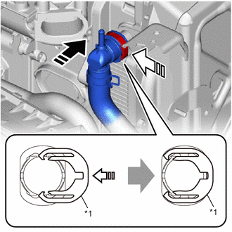
*1 Retainer 
Slowly insert 
Push in Align the EV water hose connector with the inverter with converter assembly connection portion and slowly insert it to connect the No. 1 inverter cooling hose to the inverter with converter assembly.
Note
-
When inserting the EV water hose connector, do not twist it or push it at an angle.
-
Fully and securely insert the EV water hose connector into the inverter with converter assembly connection portion.
If the 2 O-rings on the inner side of the EV water hose connector are damaged or falling out, replace the EV water hose connector with a new one.
-
-
Push in the retainer of the EV water hose connector to engage the lock.
Note
-
Push in the retainer until a click sound is heard.
-
Pull on the hose to confirm that the hose is securely connected.
-
-
To prevent contamination by foreign matter or water droplets, remove the plastic bags from the connecting portions of the No. 2 inverter cooling hose and inverter reserve tank assembly immediately before performing the procedure.
-
*a View A *b Hose end and hose clip location *c Left of vehicle *d Claw area of hose clip: 45° *e Inverter Reserve Tank Assembly Rib *f Hose paint mark (white) *g Distance from hose end to hose clip position: 2 mm (0.0787 in.) to 5 mm (0.1969 in.) mm *h Distance from hose end to stopper portion: 0 to 2 mm (0 to 0.0787 in.) mm Connect the No. 2 inverter cooling hose to the inverter reserve tank assembly and slide the hose clip to secure it.
Note
Align the hose and the hose clip at the locations shown in the illustration and install them.
-
Engage the 2 clamps to install the No. 2 inverter cooling hose to the inverter protector.
-
-
INSTALL NO. 2 INVERTER DRAIN HOSE
-
To prevent contamination by foreign matter or water droplets, remove the plastic bags from the connecting portions of the No. 2 inverter drain hose and No. 1 inverter cooling hose immediately before performing the procedure.
-
*a View A *b Hose end and hose clip location *c Front of Vehicle *d Claw area of hose clip: 45° *e EV water hose connector rib *f Hose paint mark (white) *g Distance from hose end to hose clip position: 2.0 to 5.0 mm (0.0787 to 0.1969 in.) *h Distance from hose end to stopper portion: 0 mm (0 in.) to 2 mm (0.0787 in.) mm Connect the No. 2 inverter drain hose to the EV water hose connector of the No. 1 inverter cooling hose and slide the hose clip to secure it.
Note
Align the hose and the hose clip at the locations shown in the illustration and install them.
-
Engage the 2 clamps to install the No. 2 inverter drain hose to the inverter protector.
-
To prevent contamination by foreign matter or water droplets, remove the plastic bags from the connecting portions of the No. 2 inverter drain hose and inverter reserve tank assembly immediately before performing the procedure.
-
*a View A *b Hose end and hose clip location *c Top of vehicle *d Claw area of hose clip: 45° *e Inverter reserve tank assembly rib *f Hose paint mark (yellow) *g Distance from hose end to hose clip position: 2.0 to 5.0 mm (0.0787 to 0.1969 in.) *h Distance from hose end to stopper portion: 0 to 2 mm (0 to 0.0787 in.) mm Connect the No. 2 inverter drain hose to the inverter reserve tank assembly and slide the hose clip to secure it.
Note
Align the hose and the hose clip at the locations shown in the illustration and install them.
-
-
INSTALL WATER PIPE SUB-ASSEMBLY
-
Temporarily install the water pipe sub-assembly to the FC water and hydrogen pump inverter assembly and inverter protector with the bolt and 2 nuts.
-
Fully tighten the bolt and 2 nuts in the sequence shown in the illustration.
- Torque:
- 9.8 N*m { 100 kgf*cm, 87 in.*lbf }
-
-
REMOVE INVERTER TERMINAL COVER
-
CONNECT FC CONVERTER POWER OUTLET CABLE
CAUTION:
Wear insulated gloves.
Note
Do not allow foreign matter or water droplets to enter into the inverter with converter assembly.
-
To prevent contamination by foreign matter or water droplets, only remove the protective tape covering both connector portions of the inverter with converter assembly immediately before performing work.
-
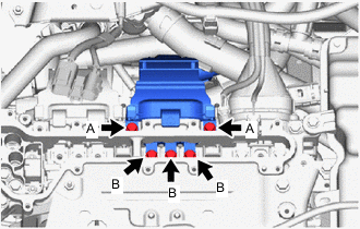
Temporarily install the FC converter power outlet cable to the inverter with converter assembly with the 5 bolts.
Note
-
To prevent damage to the threaded portion, be sure to perform the work by hand.
-
Do not touch the rubber seal or terminal portion of the connector.
-
When connecting, do not damage or scratch the terminal portions, connector housing, or inverter with converter assembly.
Tech Tips
Install bolt C directly to the terminal block of the inverter with converter assembly.
-
-
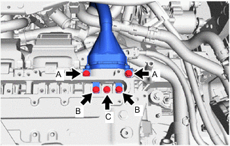
Using an insulated tool, fully tighten the 2 bolts A.
- Torque:
- 8.0 N*m { 82 kgf*cm, 71 in.*lbf }
-
Using an insulated tool, fully tighten the 2 bolts B and bolt C.
- Torque:
- 8.0 N*m { 82 kgf*cm, 71 in.*lbf }
-
-
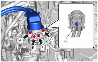
CONNECT FC AIR COMPRESSOR CABLE
CAUTION:
Wear insulated gloves.
Note
Do not allow foreign matter or water droplets to enter into the inverter with converter assembly.
-
To prevent contamination by foreign matter or water droplets, only remove the protective tape covering both connector portions of the inverter with converter assembly immediately before performing work.
-
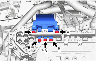
Temporarily install the FC air compressor cable to the inverter with converter assembly with the 5 bolts.
Note
-
To prevent damage to the threaded portion, be sure to perform the work by hand.
-
Do not touch the rubber seal or terminal portion of the connector.
-
When connecting, do not damage or scratch the terminal portions, connector housing, or inverter with converter assembly.
-
-
Using an insulated tool, fully tighten the 2 bolts A.
- Torque:
- 8.0 N*m { 82 kgf*cm, 71 in.*lbf }
-
Using an insulated tool, fully tighten the 3 bolts B.
- Torque:
- 8.0 N*m { 82 kgf*cm, 71 in.*lbf }
-
-
CONNECT MOTOR CABLE
CAUTION:
Wear insulated gloves.
Note
Do not allow foreign matter or water droplets to enter into the inverter with converter assembly.
-
To prevent contamination by foreign matter or water droplets, only remove the protective tape covering both connector portions of the inverter with converter assembly immediately before performing work.
-
Temporarily install the motor cable to the inverter with converter assembly with the 5 bolts.
Note
-
To prevent damage to the threaded portion, be sure to perform the work by hand.
-
Do not touch the rubber seal or terminal portion of the connector.
-
When connecting, do not damage or scratch the terminal portions, connector housing, or inverter with converter assembly.
-
-
Using an insulated tool, fully tighten the 2 bolts A.
- Torque:
- 8.0 N*m { 82 kgf*cm, 71 in.*lbf }
-
Using an insulated tool, fully tighten the 3 bolts B.
- Torque:
- 8.0 N*m { 82 kgf*cm, 71 in.*lbf }
-
-
CONNECT NO. 3 MOTOR WIRE
CAUTION:
Wear insulated gloves.
Note
Do not allow foreign matter or water droplets to enter into the inverter with converter assembly.
-
To prevent contamination by foreign matter or water droplets, only remove the protective tape covering both connector portions of the inverter with converter assembly immediately before performing work.
-
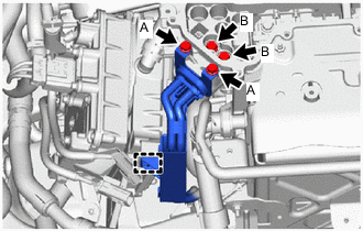
Temporarily install the No. 3 motor wire to the inverter with converter assembly with the 4 bolts.
Note
-
To prevent damage to the threaded portion, be sure to perform the work by hand.
-
Do not touch the rubber seal or terminal portion of the connector.
-
When connecting, do not damage or scratch the terminal portions, connector housing, or inverter with converter assembly.
-
-
Using an insulated tool, fully tighten the 2 bolts A.
- Torque:
- 8.0 N*m { 82 kgf*cm, 71 in.*lbf }
-
Using an insulated tool, fully tighten the 2 bolts B.
- Torque:
- 8.0 N*m { 82 kgf*cm, 71 in.*lbf }
-
Engage the clamp to install the No. 3 motor wire to the FC water and hydrogen pump inverter assembly.
-
-
INSTALL FC INVERTER INPUT JUNCTION ASSEMBLY
CAUTION:
Wear insulated gloves.
Note
Do not allow foreign matter or water droplets to enter into the inverter with converter assembly.
-
To prevent contamination by foreign matter or water droplets, only remove the protective tape covering both connector portions of the inverter with converter assembly immediately before performing work.
-
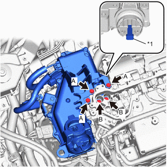
*1 Interlock Connector Temporarily install the FC inverter input junction assembly to the inverter with converter assembly with the 5 bolts.
Note
-
To prevent damage to the threaded portion, be sure to perform the work by hand.
-
Do not touch the seal packing or terminal portion of the FC inverter input junction assembly.
-
When installing, do not damage or scratch the terminal portions, connector housing, or inverter with converter assembly.
-
Securely connect the interlock connector.
Tech Tips
Bolt Type Bolt Head Shape Bolt A Flange Bolt Bolt B Bolt with Washer If the 2 O-rings on the inner side of the EV water hose connector are damaged or falling out, replace the EV water hose connector with a new one.
-
-
Using an insulated tool, fully tighten the 3 bolts A.
- Torque:
- 8.0 N*m { 82 kgf*cm, 71 in.*lbf }
-
Engage the clamp to install the No. 3 motor wire to the FC water and hydrogen pump inverter assembly.
-
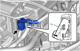
*1 Green Lock As shown in the illustration, connect the connector to the electric heater sub-assembly, push in the green lock to securely fix it in place.
Note
-
Do not touch the connector terminals.
-
Check that the connector is securely connected.
-
-
*1 Green Lock As shown in the illustration, connect the connector to the FC water and hydrogen pump inverter assembly, push in the green lock to securely fix it in place.
Note
-
Do not touch the connector terminals.
-
Check that the connector is securely connected.
-
-
Engage the clamp to install the wire harness to the FC inverter input junction assembly.
-
-
CHECK HIGH VOLTAGE CABLE CONNECTION
CAUTION:
Wear insulated gloves.
Note
Do not allow foreign matter or water droplets to enter into the inverter with converter assembly.
-
Using an insulated tool, check that each connector and terminal is securely installed.
- Torque:
- 8.0 N*m { 82 kgf*cm, 71 in.*lbf }
Note
Bolts must be tightened to the specified torque.
-
-
INSTALL INVERTER TERMINAL COVER
CAUTION:
Wear insulated gloves.
Note
Do not allow foreign matter or water droplets to enter into the inverter with converter assembly.
-
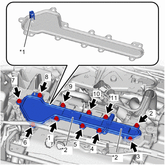
*1 Interlock Connector *2 Connector Bracket Temporarily install the inverter terminal cover with the 11 bolts to prevent any foreign matter or water from entering the inverter with converter assembly.
Note
-
Make sure that the rubber seal of the inverter terminal cover is securely installed and that no foreign matter is adhering to it, then install it.
-
Do not touch the rubber seal of the inverter terminal cover.
-
Do not install the inverter terminal cover while pressing down on the connector bracket.
-
Securely connect the interlock connector.
-
-
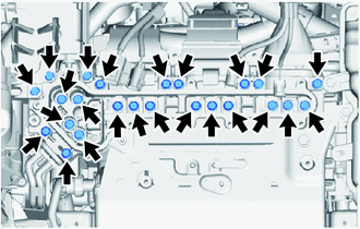
Fully tighten the 11 bolts in the sequence shown in the illustration.
- Torque:
- 8.0 N*m { 82 kgf*cm, 71 in.*lbf }
-
-
CONNECT FRAME WIRE
CAUTION:
Wear insulated gloves.
-
To prevent contamination by foreign matter or water droplets, only remove the protective tape covering both connector portions of the FC inverter input junction assembly immediately before performing work.
-
*1 Interlock Connector Temporarily install the frame wire to the FC inverter input junction assembly with the 4 bolts.
Note
-
To prevent damage to the threaded portion, be sure to perform the work by hand.
-
Do not touch the rubber seal or terminal portion of the frame wire.
-
When connecting, do not damage or scratch the terminal portions, connector housing, or FC inverter input junction assembly.
-
Securely connect the interlock connector.
Tech Tips
Bolt Type Bolt Head Shape Bolt A Flange Bolt Bolt B Bolt with Washer -
-
Using an insulated tool, fully tighten the 2 bolts A.
- Torque:
- 8.0 N*m { 82 kgf*cm, 71 in.*lbf }
-
Using an insulated tool, fully tighten the 2 bolts B.
- Torque:
- 8.0 N*m { 82 kgf*cm, 71 in.*lbf }
-
-
INSTALL FC INVERTER INPUT JUNCTION COVER
CAUTION:
Wear insulated gloves.
-
Install the FC inverter input junction cover to the FC inverter input junction assembly with the 2 bolts.
- Torque:
- 8.0 N*m { 82 kgf*cm, 71 in.*lbf }
Note
-
Do not touch the rubber seal of the FC inverter input junction cover.
-
Securely connect the interlock connector.
-
-
INSTALL FC WATER PUMP DRAIN HOSE ASSEMBLY
-
Install the FC water pump drain hose to the FC inverter input junction assembly with the bolt.
- Torque:
- 13 N*m { 133 kgf*cm, 10 ft.*lbf }
-
-
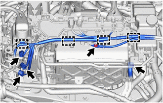
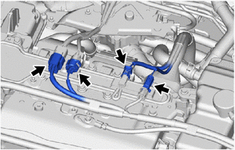
CONNECT WIRE HARNESS
CAUTION:
Wear insulated gloves.
Note
-
Check that there are no contaminants such as foreign matter or water droplets inside the connector.
-
To prevent damage from static electricity, do not touch the connector terminal portion.
-
Connect the wire harness to the inverter protector with the nut.
- Torque:
- 8.4 N*m { 86 kgf*cm, 74 in.*lbf }
-
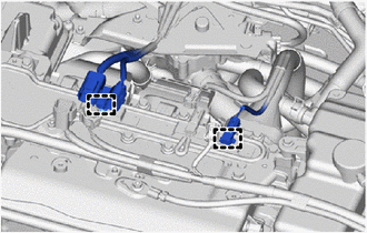
Engage the 4 clamps to install the wire harness to the FC inverter input junction cover, inverter protector and inverter reserve tank assembly.
-
Connect the 4 connectors.
-
*1 Lock Lever Engage the clamp to install the wire harness to the inverter reserve tank assembly.
-
Connect the connector and lower the lock lever to secure it.
-
Engage the 2 clamps to install the wire harness to the inverter terminal cover.
-
Connect the 4 connectors.
-
-
INSTALL INVERTER COVER
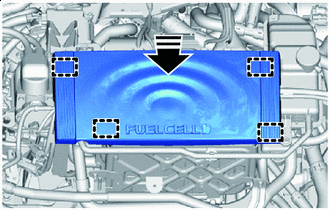
Install in this Direction
-
Install the 4 bolts to the inverter with converter assembly and inverter protector.
- Torque:
- 8.0 N*m { 82 kgf*cm, 71 in.*lbf }
-
Engage the 4 grommets to install the inverter cover to the inverter with converter assembly and inverter protector.
Note
Press the upper surface of the inverter cover grommet portion to securely engage the grommet.
-
-
INSTALL AIR CLEANER ASSEMBLY WITH ELEMENT
-
INSTALL AIR CLEANER INLET
-
INSTALL COOL AIR INTAKE DUCT SEAL
-
INSTALL OUTER COWL TOP PANEL SUB-ASSEMBLY (for LHD)
-
INSTALL OUTER COWL TOP PANEL SUB-ASSEMBLY (for RHD)
-
INSTALL COWL BODY MOUNTING REINFORCEMENT RH (for LHD)
-
INSTALL COWL BODY MOUNTING REINFORCEMENT RH (for RHD)
-
INSTALL WATER GUARD PLATE LH (for LHD)
-
INSTALL WATER GUARD PLATE RH (for RHD)
-
INSTALL NO. 2 HEATER AIR DUCT SPLASH SHIELD SEAL (for LHD)
-
INSTALL NO. 1 HEATER AIR DUCT SPLASH SHIELD SEAL (for RHD)
-
INSTALL WINDSHIELD WIPER MOTOR AND LINK
-
INSTALL FC STACK SERVICE PLUG GRIP
-
INSTALL SERVICE PLUG GRIP (for EV)
-
ADD INVERTER COOLANT
-
INSPECT FOR INVERTER COOLANT LEAK
-
INSTALL NO. 3 RADIATOR AIR GUIDE
-
INSTALL LOWER FRONT BUMPER ABSORBER