HYBRID BATTERY SYSTEM, Diagnostic DTC:P0A80-123
| DTC Code | DTC Name |
|---|---|
| P0A80-123 | Replace Battery Pack |
DESCRIPTION
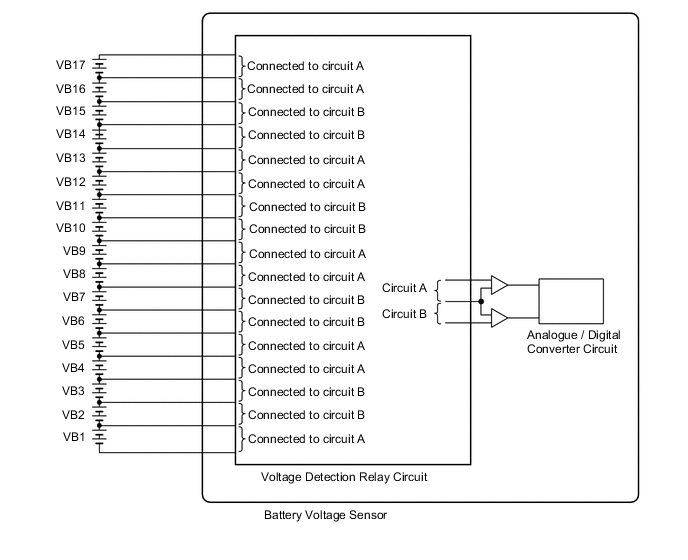
The EV control ECU controls the SOC (state of charge) of the EV battery at a constant level during driving. The EV battery is composed of 34 modules, and each module consists of six 1.2 V cells in series. The battery voltage sensor monitors battery block voltage at 17 locations. Each battery block is composed of 2 modules in a set.
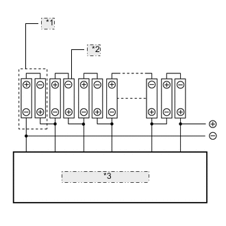
| *1 | Battery Block |
| *2 | Battery Module |
| *3 | Battery Voltage Sensor |
| DTC No. | Detection Item | DTC Detection Condition | Trouble Area | Warning Indicate |
|---|---|---|---|---|
| P0A80-123 | Replace Battery Pack | Voltage difference between battery blocks is larger than the specified value due to an internal malfunction of the EV battery. (2 trip detection logic) |
|
Master Warning Light: Comes on |
| DTC No. | Data List |
|---|---|
| P0A80-123 |
|
The following items can be helpful when performing repairs:
-
Ready Signal
-
Vehicle Speed
-
Accelerator Degree
-
Shift Sensor Shift Position
-
Internal Resistance R01 to R17
-
VB-Battery Voltage
-
Battery Pack Current Value (IB Correction)
-
Auxiliary Battery Voltage
-
Battery Voltage Low Time
-
DC Discharge Inhibit Time
-
SOC after IG-ON
-
Status of Charge Max
-
Status of Charge Min
-
Total Distance Traveled
Data List (EV)
-
FC Mode
-
FC Intermittent Operation
-
FC Voltage before Boosting
-
FC Current
-
Hydrogen Remaining
Data List (FC)
-
Battery Low Voltage-Last Operation
-
Battery Low Voltage-Last Trip
Operation History Data
Tech Tips
-
This DTC can be stored after clearing DTCs and driving the vehicle for approximately 10 minutes. (As 2 trip detection logic is used, check for DTCs including pending DTCs.)
-
DTC P0A80-123 is stored when a malfunction is detected in the EV battery or battery voltage sensor. If the EV battery is malfunctioning, the malfunction may not be reproduced when the condition of the EV battery changes due to a difference in driving load (amperage), battery SOC and battery temperature. Therefore, use the freeze frame data when performing a repair.
-
When the EV battery is malfunctioning:
-
- Voltage of 1 or a few battery blocks has dropped. (Voltage difference from that of the next block is 1 V or more.)
-
- Voltage of all battery blocks is output randomly with no certain pattern.
-
When the battery voltage sensor is malfunctioning:
-
- Differences in battery block voltages have a certain pattern.
-
In order to ensure EV battery performance, appropriate cooling performance must be maintained. Perform the following items as necessary. If cooling performance has decreased and "MAINTENANCE REQUIRED FOR HYBRID BATTERY COOLING PARTS AT YOUR DEALER" is displayed on the multi-information display, make sure to perform the following items:
- Make sure the air intake port is not blocked.
- Make sure there are no gaps between the connecting parts of the ducts.
- Clean the No. 1 EV battery intake duct (filter).
Afterwards, clear the DTCs to reset the learning values even if no DTCs are stored.
CAUTION / NOTICE / HINT
Note
When the vehicle is parked with the power switch off, if the FC control ECU judges that the FC stack temperature will go below 0°C (32°F), it activates the FC air compressor, hydrogen pump and FC cooling water pump for a maximum of 180 seconds and drains water from the FC stack assembly. When performing inspection or repairs with the power switch off (not on (IG) or on (READY)), disconnect the cable from the negative (-) auxiliary battery terminal before performing work (If the auxiliary battery voltage is needed to conduct inspection, warm up the FC system beforehand).
Tech Tips
When disposing of an EV battery, make sure to return it through an authorized collection agent who is capable of handling it safely. If the EV battery is returned via the manufacturer specified route, it will be returned properly and in a safe manner by an authorized collection agent.
PROCEDURE
-
CHECK DTC OUTPUT (EV)
Result Result Proceed to P0AFC-123 is not output. A P0AFC-123 is also output. B
-
Connect the GTS to the DLC3.
-
Turn the power switch on (IG).
-
Enter the following menus: Powertrain / EV / Trouble Codes.
-
Check and record any hybrid control system DTCs, INF codes and freeze frame data.
-
Read output DTCs.
Powertrain > EV > Trouble CodesResult Result Proceed to P0AFC-123 is not output. A P0AFC-123 is also output. B -
Turn the power switch off.
-
Disconnect the GTS from the DLC3.
B 
GO TO DTC CHART (P0AFC-123) Click here
A 
-
-
CHECK FREEZE FRAME DATA
-
Connect the GTS to the DLC3.
-
Turn the power switch on (IG).
-
Enter the following menus: Powertrain / EV / Trouble Codes.
-
Read output DTCs.
Powertrain > EV > Trouble Codes -
Using the GTS, make a note of the freeze frame data item "Battery Block Voltage -V01 to V17".
-
Compare the freeze frame data item "Battery Block Voltage -V01 to V17" values with those shown in the following combination tables.
Table 1 Circuit A Battery Block Circuit B Battery Block Condition Battery Block Voltage -V01 (VB1) Battery Block Voltage -V02 (VB2) "Battery Block Voltage -V01" - "Battery Block Voltage -V02" = 0.3 V or more Battery Block Voltage -V04 (VB4) Battery Block Voltage -V03 (VB3) "Battery Block Voltage -V04" - "Battery Block Voltage -V03" = 0.3 V or more Battery Block Voltage -V05 (VB5) Battery Block Voltage -V06 (VB6) "Battery Block Voltage -V05" - "Battery Block Voltage -V06" = 0.3 V or more Battery Block Voltage -V08 (VB8) Battery Block Voltage -V07 (VB7) "Battery Block Voltage -V08" - "Battery Block Voltage -V07" = 0.3 V or more Battery Block Voltage -V09 (VB9) Battery Block Voltage -V10 (VB10) "Battery Block Voltage -V09" - "Battery Block Voltage -V10" = 0.3 V or more Battery Block Voltage -V12 (VB12) Battery Block Voltage -V11 (VB11) "Battery Block Voltage -V12" - "Battery Block Voltage -V11" = 0.3 V or more Battery Block Voltage -V13 (VB13) Battery Block Voltage -V14 (VB14) "Battery Block Voltage -V13" - "Battery Block Voltage -V14" = 0.3 V or more Battery Block Voltage -V16 (VB16) Battery Block Voltage -V15 (VB15) "Battery Block Voltage -V16" - "Battery Block Voltage -V15" = 0.3 V or more Battery Block Voltage -V17 (VB17) Battery Block Voltage -V14 (VB14) "Battery Block Voltage -V17" - "Battery Block Voltage -V14" = 0.3 V or more Table 2 Circuit A Battery Block Circuit B Battery Block Condition Battery Block Voltage -V01 (VB1) Battery Block Voltage -V02 (VB2) "Battery Block Voltage -V02" - "Battery Block Voltage -V01" = 0.3 V or more Battery Block Voltage -V04 (VB4) Battery Block Voltage -V03 (VB3) "Battery Block Voltage -V03" - "Battery Block Voltage -V04" = 0.3 V or more Battery Block Voltage -V05 (VB5) Battery Block Voltage -V06 (VB6) "Battery Block Voltage -V06" - "Battery Block Voltage -V05" = 0.3 V or more Battery Block Voltage -V08 (VB8) Battery Block Voltage -V07 (VB7) "Battery Block Voltage -V07" - "Battery Block Voltage -V08" = 0.3 V or more Battery Block Voltage -V09 (VB9) Battery Block Voltage -V10 (VB10) "Battery Block Voltage -V10" - "Battery Block Voltage -V09" = 0.3 V or more Battery Block Voltage -V12 (VB12) Battery Block Voltage -V11 (VB11) "Battery Block Voltage -V11" - "Battery Block Voltage -V12" = 0.3 V or more Battery Block Voltage -V13 (VB13) Battery Block Voltage -V14 (VB14) "Battery Block Voltage -V14" - "Battery Block Voltage -V13" = 0.3 V or more Battery Block Voltage -V16 (VB16) Battery Block Voltage -V15 (VB15) "Battery Block Voltage -V15" - "Battery Block Voltage -V16" = 0.3 V or more Battery Block Voltage -V17 (VB17) Battery Block Voltage -V14 (VB14) "Battery Block Voltage -V14" - "Battery Block Voltage -V17" = 0.3 V or more Tech Tips
Make sure to compare Battery Block Voltage -V17 to Battery Block Voltage -V14 in accordance with the tables above.
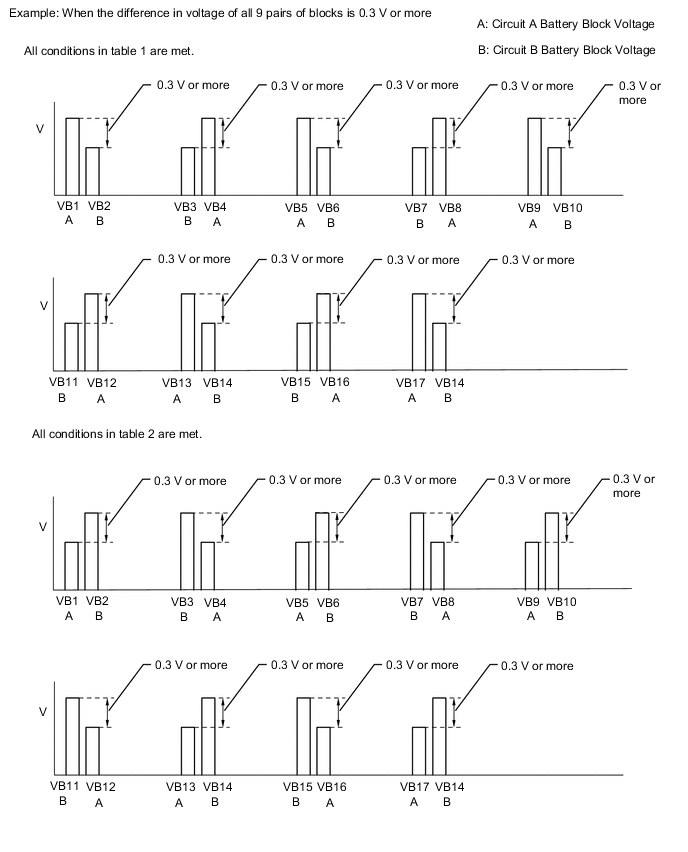
Tech Tips
When an internal malfunction occurs in the battery voltage sensor, this symptom (difference in voltage of 0.3 V or more for all 9 pairs of blocks) will occur.
Result Result Proceed to All conditions in table 1 or table 2 are met. A Other than above B -
Turn the power switch off.
-
Disconnect the GTS from the DLC3.
A
REPLACE BATTERY VOLTAGE SENSOR Click here
B
REPLACE EV BATTERY Click here
-