HYBRID CONTROL SYSTEM ECU Power Source Circuit
DESCRIPTION
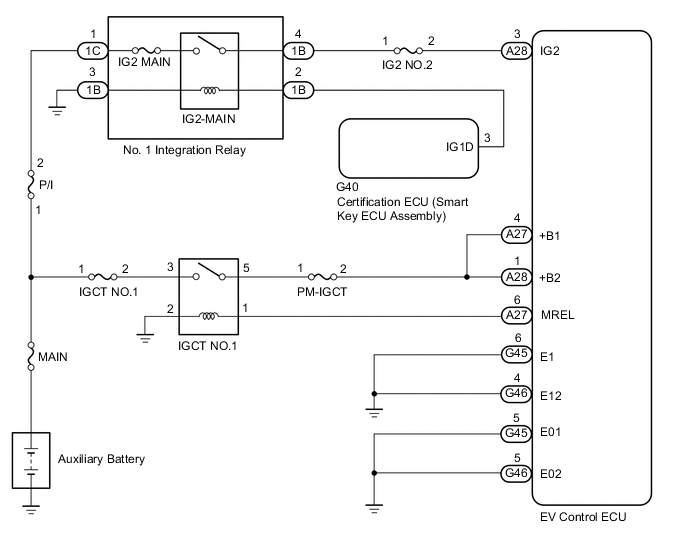
With the power switch is turned on (IG), the certification ECU (smart key ECU assembly) sends current to the IG1D terminal and turns the IG2 main relay on.
In this way, a power source is supplied to the IG2 terminal of the of the EV control ECU.
If the power switch is on (IG), the EV control ECU applies current to the MREL terminal to turn the IGCT relay on. This supplies power to the +B1 and +B2 terminals.
WIRING DIAGRAM
Refer to the wiring diagram for DTC P0A08-264.
CAUTION / NOTICE / HINT
Note
When the vehicle is parked with the power switch off, if the FC control ECU judges that the FC stack temperature will go below 0°C (32°F), it activates the FC air compressor, hydrogen pump and FC cooling water pump for a maximum of 180 seconds and drains water from the FC stack assembly. When performing inspection or repairs with the power switch off (not on (IG) or on (READY)), disconnect the cable from the negative (-) auxiliary battery terminal before performing work (If the auxiliary battery voltage is needed to conduct inspection, warm up the FC system beforehand).
PROCEDURE
-
CHECK TERMINAL VOLTAGE (+B1, +B2 VOLTAGE)
-
Turn the power switch on (IG).
-
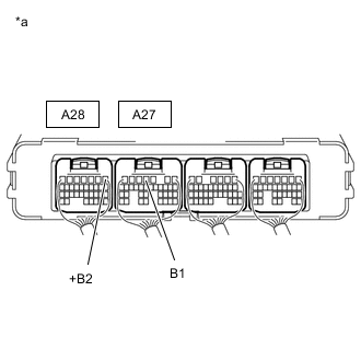
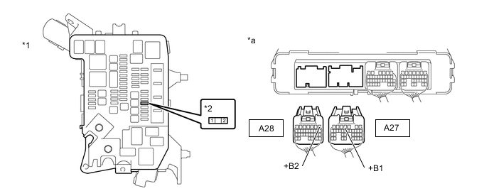
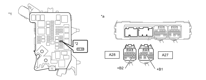
*a Component with harness connected
(EV Control ECU)
Measure the voltage according to the value(s) in the table below.
Standard Voltage Tester Connection Condition Specified Condition A27-4 (+B1) - Body ground Power switch on (IG) 11 to 14 V A28-1 (+B2) - Body ground Power switch on (IG) 11 to 14 V -
Turn the power switch off.
Result Proceed to OK NG
NG 
CHECK EV CONTROL ECU (MREL VOLTAGE) Click here
OK 
-
-
CHECK TERMINAL VOLTAGE (IG2 VOLTAGE)
-
Turn the power switch on (IG).
-
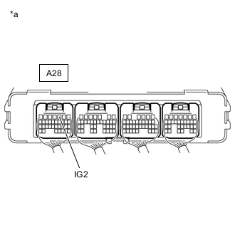
*a Component with harness connected
(EV Control ECU)
Measure the voltage according to the value(s) in the table below.
Standard Voltage Tester Connection Condition Specified Condition A28-3 (IG2) - Body ground Power switch on (IG) 11 to 14 V -
Turn the power switch off.
Result Proceed to OK NG
NG
CHECK INTEGRATION RELAY (SOURCE VOLTAGE) Click here
OK
-
-
CHECK HARNESS AND CONNECTOR (EV CONTROL ECU - BODY GROUND)
-
Disconnect the EV control ECU connectors.
-
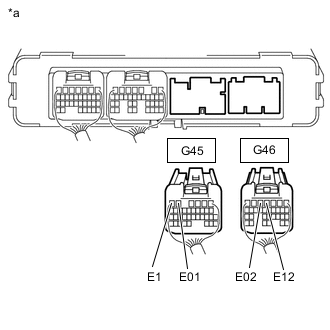
*a Rear view of wire harness connector
(to EV Control ECU)
Measure the resistance according to the value(s) in the table below.
Standard Resistance Tester Connection Condition Specified Condition G45-5 (E01) - Body ground Always Below 1 Ω G45-6 (E1) - Body ground Always Below 1 Ω G46-4 (E12) - Body ground Always Below 1 Ω G46-5 (E02) - Body ground Always Below 1 Ω -
Reconnect the EV control ECU connectors.
Result Proceed to OK NG
OK 
GO TO PROBLEM SYMPTOMS TABLE
NG
REPAIR OR REPLACE HARNESS OR CONNECTOR
-
-
CHECK INTEGRATION RELAY (SOURCE VOLTAGE)
-
Remove the No.1 integration relay from the motor compartment relay block.
-
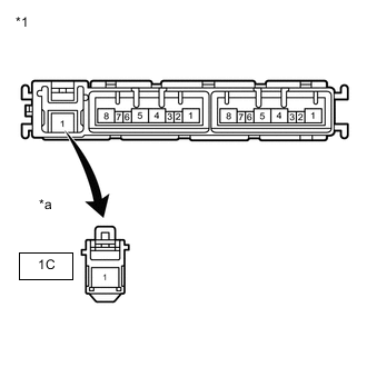
*1 No. 1 Integration Relay *a Front view of wire harness connector
(to No. 1 Integration relay)
Measure the voltage according to the value(s) in the table below.
Standard Resistance Tester Connection Condition Specified Condition 1C-1 - Body ground Power switch off 11 to 14 V -
Install the No.1 integration relay.
Result Proceed to OK NG
NG
CHECK FUSIBLE LINK (P/I) Click here
OK
-
-
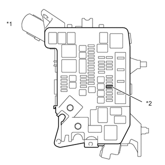
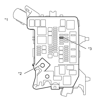
CHECK FUSE (IG2 NO.2)
-
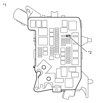
*1 Motor Compartment Relay Block *2 IG2 NO.2 Fuse Remove the IG2 NO.2 fuse from the motor compartment relay block.
-
Measure the resistance according to the value(s) in the table below.
Standard Resistance Tester Connection Condition Specified Condition IG2 NO.2 fuse terminals Always Below 1 Ω -
Install the IG2 NO.2 fuse.
Result Proceed to OK NG
NG
REPLACE FUSES (IG2 NO.2)
OK
-
-
INSPECT NO.1 INTEGRATION RELAY (IG2 MAIN RELAY)
-
Remove the No.1 integration relay from the motor compartment relay block.
-
Inspect the IG2 MAIN relay.
-
Install the No.1 integration relay.
Result Proceed to OK NG
NG
REPLACE NO.1 INTEGRATION RELAY Click here
OK
-
-
CHECK HARNESS AND CONNECTOR (NO.1 INTEGRATION RELAY - BODY GROUND)
-
Remove the No.1 integration relay from the motor compartment relay block.
-
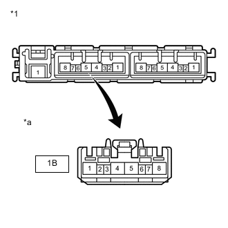
*1 No. 1 Integration Relay *a Front view of wire harness connector
(to No. 1 Integration relay)
Measure the resistance according to the value(s) in the table below.
Standard Resistance Tester Connection Condition Specified Condition 1B-3 - Body ground Power switch off Below 1 Ω -
Install the No.1 integration relay.
Result Proceed to OK NG
NG
REPAIR OR REPLACE HARNESS OR CONNECTOR
OK
-
-
CHECK HARNESS AND CONNECTOR (NO.1 INTEGRATION RELAY - EV CONTROL ECU)
-
Remove the No.1 integration relay from the motor compartment relay block.
-
Disconnect the EV control ECU connectors.
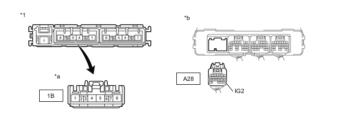
*1 No. 1 Integration Relay - - *a Front view of wire harness connector
(to No. 1 Integration relay)
*b Rear view of wire harness connector
(to EV Control ECU)
-
Measure the resistance according to the value(s) in the table below.
Standard Resistance Tester Connection Condition Specified Condition 1B-4 - A28-3 (IG2) Power switch off Below 1 Ω 1B-4 or A28-3 (IG2) - Body ground Power switch off 10 kΩ or higher -
Reconnect the EV control ECU connectors.
-
Install the No.1 integration relay.
Result Proceed to OK NG
NG
REPAIR OR REPLACE HARNESS OR CONNECTOR
OK
-
-
CHECK HARNESS AND CONNECTOR (NO.1 INTEGRATION RELAY - SMART KEY ECU ASSEMBLY)
-
Remove the No.1 integration relay from the motor compartment relay block.
-
Disconnect the certification ECU (smart key ECU assembly) connector.
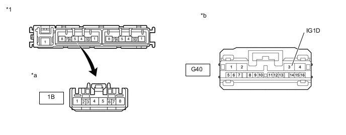
*1 No. 1 Integration Relay - - *a Front view of wire harness connector
(to No. 1 Integration relay)
*b Front view of wire harness connector
(to Certification ECU (Smart Key ECU Assembly))
-
Measure the resistance according to the value(s) in the table below.
Standard Resistance Tester Connection Condition Specified Condition 1B-2 - G40-3 (IG1D) Power switch off Below 1 Ω 1B-2 or G40-3 (IG1D) - Body ground Power switch off 10 kΩ or higher -
Reconnect the certification ECU (smart key ECU assembly) connector.
-
Install the No.1 integration relay.
Result Proceed to OK NG
OK
CHECK ENTRY AND START SYSTEM Click here
NG
REPAIR OR REPLACE HARNESS OR CONNECTOR
-
-
CHECK FUSIBLE LINK (P/I)
-
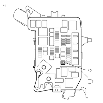
*1 Motor Compartment Relay Block *2 Fusible Link (P/I) Remove the fusible link (P/I) from the motor compartment relay block.
-
Measure the resistance according to the value(s) in the table below.
Standard Resistance Tester Connection Condition Specified Condition Fusible link (P/I) fuse terminals Always Below 1 Ω -
Install the fusible link (P/I).
Result Proceed to OK NG
OK
REPAIR OR REPLACE HARNESS OR CONNECTOR (NO.1 INTEGRATION RELAY - AUXILIARY BATTERY)
NG
REPLACE FUSIBLE LINK (P/I)
-
-
CHECK EV CONTROL ECU (MREL VOLTAGE)
-
Turn the power switch on (IG).
-
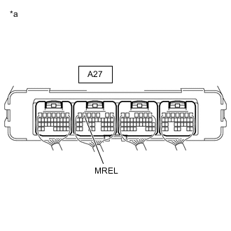
*a Component with harness connected
(EV Control ECU)
Measure the voltage according to the value(s) in the table below.
Standard Voltage Tester Connection Condition Specified Condition A27-6 (MREL) - Body ground Power switch on (IG) 11 to 14 V -
Turn the power switch off.
Result Proceed to OK NG
NG
REPLACE EV CONTROL ECU Click here
OK
-
-
CHECK FUSE (PM-IGCT)
-

*1 Motor Compartment Relay Block *2 PM-IGCT Fuse Remove the PM-IGCT fuse from the motor compartment relay block.
-
Measure the resistance according to the value(s) in the table below.
Standard Resistance Tester Connection Condition Specified Condition PM-IGCT fuse terminals Always Below 1 Ω -
Install the PM-IGCT fuse.
Result Proceed to OK NG
NG
CHECK HARNESS AND CONNECTOR (EV CONTROL ECU - MOTOR COMPARTMENT RELAY BLOCK) Click here
OK
-
-
CHECK FUSE (IGCT NO.1)
-
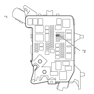
*1 Motor Compartment Relay Block *2 IGCT NO.1 Fuse Remove the IGCT NO.1 fuse from the motor compartment relay block.
-
Measure the resistance according to the value(s) in the table below.
Standard Resistance Tester Connection Condition Specified Condition IGCT NO.1 fuse terminals Always Below 1 Ω -
Install the IGCT NO.1 fuse.
Result Proceed to OK NG
NG
CHECK HARNESS AND CONNECTOR (MOTOR COMPARTMENT RELAY BLOCK) Click here
OK
-
-
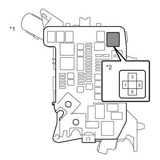
INSPECT IGCT NO. 1 RELAY (IGCT NO.1)
-
Remove the IGCT NO.1 relay from the motor compartment relay block.
-
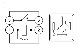
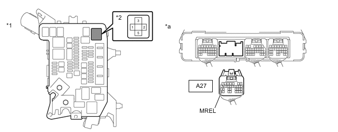
*1 IGCT NO.1 Relay Measure the resistance according to the value(s) in the table below.
Standard Resistance Tester Connection Condition Specified Condition 3 - 5 Auxiliary battery voltage not applied between terminals 1 and 2 10 kΩ or higher Auxiliary battery voltage applied between terminals 1 and 2 Below 1 Ω -
Install the IGCT NO.1 relay.
Result Proceed to OK NG
NG
REPLACE IGCT NO. 1 RELAY
OK
-
-
CHECK HARNESS AND CONNECTOR (EV CONTROL ECU - MOTOR COMPARTMENT RELAY BLOCK)
-
*1 Motor Compartment Relay Block *2 PM-IGCT Fuse Remove the PM-IGCT fuse from the motor compartment relay block.
-
Disconnect the EV control ECU connectors.
-
Measure the resistance according to the value(s) in the table below.
*1 Motor Compartment Relay Block *2 PM-IGCT Fuse Holder *a Rear view of wire harness connector
(to EV Control ECU)
- - Standard Resistance Tester Connection Condition Specified Condition A27-4 (+B1) - 2 (PM-IGCT fuse holder) Always Below 1 Ω A28-1 (+B2) - 2 (PM-IGCT fuse holder) Always Below 1 Ω -
Install the PM-IGCT fuse.
-
Reconnect the EV control ECU connectors.
Result Proceed to OK NG
NG
REPAIR OR REPLACE HARNESS OR CONNECTOR
OK
-
-
CHECK HARNESS AND CONNECTOR (MOTOR COMPARTMENT RELAY BLOCK)
-
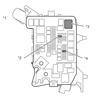
*1 Motor Compartment Relay Block *2 IGCT NO.1 Fuse *3 IGCT NO.1 Relay *4 PM-IGCT Fuse Remove the IGCT NO.1 fuse, PM-IGCT fuse and IGCT NO.1 relay from the motor compartment relay block.
-
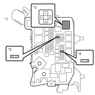
*1 Motor Compartment Relay Block *2 IGCT NO.1 Fuse Holder *3 IGCT NO.1 Relay Holder *4 PM-IGCT Fuse Holder Measure the resistance according to the value(s) in the table below.
Standard Resistance Tester Connection Condition Specified Condition 3 (IGCT NO.1 relay holder) - 2 (IGCT NO.1 fuse holder) Always Below 1 Ω 5 (IGCT NO.1 relay holder) - 1 (PM-IGCT fuse holder) Always Below 1 Ω -
Install the IGCT NO.1 fuse, PM-IGCT fuse and IGCT NO.1 relay.
Result Proceed to OK NG
NG
REPAIR OR REPLACE HARNESS OR CONNECTOR
OK
-
-
CHECK HARNESS AND CONNECTOR (EV CONTROL ECU - MOTOR COMPARTMENT RELAY BLOCK)
-
Remove the IGCT NO.1 relay from the motor compartment relay block.
-
Disconnect the EV control ECU connectors.
-
Measure the resistance according to the value(s) in the table below.
*1 Motor Compartment Relay Block *2 IGCT NO.1 Relay Holder *a Rear view of wire harness connector
(to EV Control ECU)
- - Standard Resistance Tester Connection Condition Specified Condition A27-6 (MREL) - 1 (IGCT NO.1 relay holder) Always Below 1 Ω A27-6 (MREL) or 1 (IGCT NO.1 relay holder) - Body ground and other terminals Always 10 kΩ or higher -
Install the IGCT NO.1 relay.
-
Reconnect the EV control ECU connectors.
Result Proceed to OK NG
NG
REPAIR OR REPLACE HARNESS OR CONNECTOR
OK
-
-
CHECK HARNESS AND CONNECTOR (MOTOR COMPARTMENT RELAY BLOCK - BODY GROUND)
-
Remove the IGCT NO.1 relay from the motor compartment relay block.
-
*1 Motor Compartment Relay Block *2 IGCT NO.1 Relay Holder Measure the resistance according to the value(s) in the table below.
Standard Resistance Tester Connection Condition Specified Condition 2 (IGCT NO.1 relay holder) - Body ground Always Below 1 Ω -
Install the IGCT NO.1 relay.
Result Proceed to OK NG
NG
REPAIR OR REPLACE HARNESS OR CONNECTOR
OK
-
-
CHECK HARNESS AND CONNECTOR (MOTOR COMPARTMENT RELAY BLOCK)
-
Disconnect the No. 2 motor compartment main wire from the AMD terminal (motor compartment relay block side).
-
*1 Motor Compartment Relay Block *2 AMD Terminal *3 IGCT NO.1 Fuse Remove the IGCT NO.1 fuse from the motor compartment relay block.
-
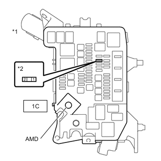
*1 Motor Compartment Relay Block *2 IGCT NO.1 Fuse Holder Measure the resistance according to the value(s) in the table below.
Standard Resistance Tester Connection Condition Specified Condition 1C-1 (AMD) - 1 (IGCT NO.1 fuse holder) Always Below 1 Ω -
Reconnect the No. 2 motor compartment main wire.
-
Install the IGCT NO.1 relay.
Result Proceed to OK NG
OK
CHECK INTERMITTENT PROBLEMS
NG
-
-
CHECK FUSES (DC/DC)
Result Proceed to OK NG CAUTION:
Be sure to wear insulated gloves.
-
Disconnect the cable to the negative (-) auxiliary battery terminal.
-
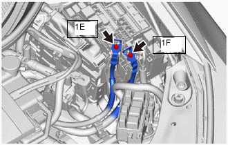
Disconnect the 1E motor compartment relay block terminal.
-
Disconnect the 1F motor compartment relay block terminal.
-
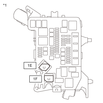
*1 Motor Compartment Relay Block Measure the resistance according to the value(s) in the table below.
Standard Resistance Tester Connection Condition Specified Condition 1E-1 - 1F-1 Always Below 1 Ω -
Reconnect the 1F motor compartment relay block terminal.
-
Reconnect the 1E motor compartment relay block terminal.
-
Reconnect the cable to the negative (-) auxiliary battery terminal.
Result Proceed to OK NG
OK
REPAIR OR REPLACE HARNESS OR CONNECTOR
NG
REPLACE FUSES (DC/DC)
-
-
CHECK HARNESS AND CONNECTOR (MOTOR COMPARTMENT RELAY BLOCK)
-
*1 Motor Compartment Relay Block *2 IGCT NO.1 Fuse *3 IGCT NO.1 Relay *4 PM-IGCT Fuse Remove the IGCT NO.1 fuse, PM-IGCT fuse and IGCT NO.1 relay from the motor compartment relay block.
-
*1 Motor Compartment Relay Block *2 IGCT NO.1 Fuse Holder *3 IGCT NO.1 Relay Holder *4 PM-IGCT Fuse Holder Measure the resistance according to the value(s) in the table below.
Standard Resistance Tester Connection Condition Specified Condition 3 (IGCT NO.1 relay holder) or 2 (IGCT NO.1 fuse holder) - Body ground and other terminals Always 10 kΩ or higher 5 (IGCT NO.1 relay holder) or 1 (IGCT NO.1 fuse holder) - Body ground and other terminals Always 10 kΩ or higher -
Install the IGCT NO.1 fuse, PM-IGCT fuse and IGCT NO.1 relay.
Result Proceed to OK NG
OK
REPLACE FUSES (IGCT NO.1)
NG
-
-
REPAIR OR REPLACE HARNESS OR CONNECTOR
Result Proceed to NEXT
NEXT
REPLACE FUSES (IGCT NO.1)
-
CHECK HARNESS AND CONNECTOR (EV CONTROL ECU - MOTOR COMPARTMENT RELAY BLOCK)
-

*1 Motor Compartment Relay Block *2 PM-IGCT Fuse Remove the PM-IGCT fuse from the motor compartment relay block.
-
Disconnect the EV control ECU connectors.
-
Measure the resistance according to the value(s) in the table below.
*1 Motor Compartment Relay Block *2 PM-IGCT Fuse Holder *a Rear view of wire harness connector
(to EV Control ECU)
- - Standard Resistance Tester Connection Condition Specified Condition A27-4 (+B1) or 2 (PM-IGCT fuse holder) - Body ground and other terminals Always 10 kΩ or higher A28-1 (+B2) or 2 (PM-IGCT fuse holder) - Body ground and other terminals Always 10 kΩ or higher -
Install the PM-IGCT fuse.
-
Reconnect the EV control ECU connectors.
Result Proceed to OK NG
OK
REPLACE FUSES (PM-IGCT)
NG
-
-
REPAIR OR REPLACE HARNESS OR CONNECTOR
Result Proceed to NEXT
NEXT
REPLACE FUSES (PM-IGCT)