HYBRID CONTROL SYSTEM Pattern Select Switch Power Mode Circuit
DESCRIPTION
The PWR mode signal will be sent to the EV control ECU when the POWER MODE switch (integration control and panel assembly) is operated. If the specified conditions are met, the system enters PWR mode and the vehicle will be driven using PWR mode. This signal is then transmitted from the EV control ECU via CAN to the combination meter assembly to illuminate the PWR mode indicator.
WIRING DIAGRAM
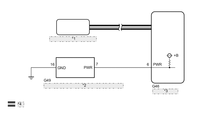
| *1 | Combination Meter Assembly |
| *2 | POWER MODE Switch (Integration Control and Panel Assembly) |
| *3 | EV Control ECU |
| *4 | CAN Communication Line |
CAUTION / NOTICE / HINT
Note
When the vehicle is parked with the power switch off, if the FC control ECU judges that the FC stack temperature will go below 0°C (32°F), it activates the FC air compressor, hydrogen pump and FC cooling water pump for a maximum of 180 seconds and drains water from the FC stack assembly. When performing inspection or repairs with the power switch off (not on (IG) or on (READY)), disconnect the cable from the negative (-) auxiliary battery terminal before performing work (If the auxiliary battery voltage is needed to conduct inspection, warm up the FC system beforehand).
PROCEDURE
-
READ VALUE USING GTS (CAN BUS CHECK)
-
Connect the GTS to the DLC3.
-
Turn the power switch on (IG).
-
Enter the following menus: System Select / CAN Bus Check.
CAN Bus CheckResult Result Proceed to All of the ECUs and sensors that are currently connected to the CAN communication system are displayed. A None of the ECUs and sensors that are currently connected to the CAN communication system are displayed, or some of them are not displayed.(for LHD) B None of the ECUs and sensors that are currently connected to the CAN communication system are displayed, or some of them are not displayed.(for RHD) C -
Turn the power switch off.
B 
GO TO CAN COMMUNICATION SYSTEM (for LHD) Click here
C
GO TO CAN COMMUNICATION SYSTEM (for RHD) Click here
A 
-
-
CHECK DTC OUTPUT (HEALTH CHECK)
-
Connect the GTS to the DLC3.
-
Turn the power switch on (IG).
-
Enter the following menus: System Select / Health Check.
-
Check for DTCs.
Result Result Proceed to No DTCs are output. A DTCs are output. B -
Turn the power switch off.
B
GO TO DTC CHART
A
-
-
READ VALUE USING GTS (PATTERN SWITCH (PWR/M), POWER MODE SWITCH)
-
Connect the GTS to the DLC3.
-
Turn the power switch on (IG).
-
Enter the following menus: Powertrain / EV / Data List / Pattern Switch (PWR/M), Power Mode Switch.
Powertrain > EV > Data ListTester Display Pattern Switch (PWR/M) Power Mode Switch -
Read the value displayed on the GTS.
Powertrain > EV > Data ListTester Display Measurement Item Range Normal Condition Pattern Switch (PWR/M) PWR mode transition availability ON or OFF In PWR mode: ON Power Mode Switch POWER MODE switch (integration control and panel assembly) condition ON or OFF POWER MODE switch (integration control and panel assembly) being pushed and held: ON Result Result Proceed to The GTS display changes according to the POWER MODE switch (integration control and panel assembly) operation. A The GTS display does not change according to the POWER MODE switch (integration control and panel assembly) operation. B -
Turn the power switch off.
A
CHECK FOR INTERMITTENT PROBLEMS Click here
B
-
-
INSPECT EV CONTROL ECU
-
Disconnect the integration control and panel assembly connector.
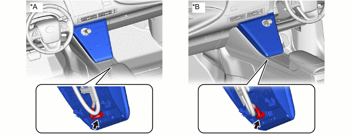
*A for LHD *B for RHD -
Turn the power switch on (IG).
-
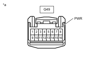
*a Front view of wire harness connector
(to Integration Control and Panel Assembly)
Measure the voltage according to the value(s) in the table below.
Standard Voltage Tester Connection Condition Specified Condition G49-7 (PWR) - Body ground Power switch on (IG) 11 to 14 V -
Turn the power switch off.
-
Reconnect the integration control and panel assembly connector.
Result Proceed to OK NG
NG 
CHECK HARNESS AND CONNECTOR (EV CONTROL ECU - INTEGRATION CONTROL AND PANEL ASSEMBLY) Click here
OK
-
-
CHECK WIRE HARNESS AND CONNECTOR (INTEGRATION CONTROL AND PANEL ASSEMBLY - BODY GROUND)
-
Remove the integration control and panel assembly.
-
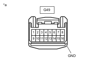
*a Front view of wire harness connector
(Integration Control and Panel Assembly)
Measure the resistance according to the value(s) in the table below.
Standard Resistance Tester Connection Condition Specified Condition G49-16 (GND) - Body ground Always Below 1 Ω -
Install the integration control and panel assembly.
Result Proceed to OK NG
OK
REPLACE INTEGRATION CONTROL AND PANEL ASSEMBLY Click here
NG
REPAIR OR REPLACE HARNESS OR CONNECTOR
-
-
CHECK HARNESS AND CONNECTOR (EV CONTROL ECU - INTEGRATION CONTROL AND PANEL ASSEMBLY)
-
Disconnect the EV control ECU connector.
-
Disconnect the integration control and panel assembly connector.
-
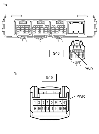
*a Rear view of wire harness connector
(to EV Control ECU)
*b Front view of wire harness connector
(to Integration Control and Panel Assembly)
Measure the resistance according to the value(s) in the table below.
Standard Resistance Tester Connection Condition Specified Condition G46-6 (PWR) - G49-7 (PWR) Always Below 1 Ω G46-6 (PWR) or G49-7 (PWR) - Body ground Always 10 kΩ or higher -
Reconnect the integration control and panel assembly connector.
-
Reconnect the EV control ECU connector.
Result Proceed to OK NG
OK
REPLACE EV CONTROL ECU Click here
NG
REPAIR OR REPLACE HARNESS OR CONNECTOR
-