FRAME WIRE INSTALLATION
PROCEDURE
-
INSTALL FRAME WIRE
-
Engage the 2 claws and install the new clamps to the frame wire.
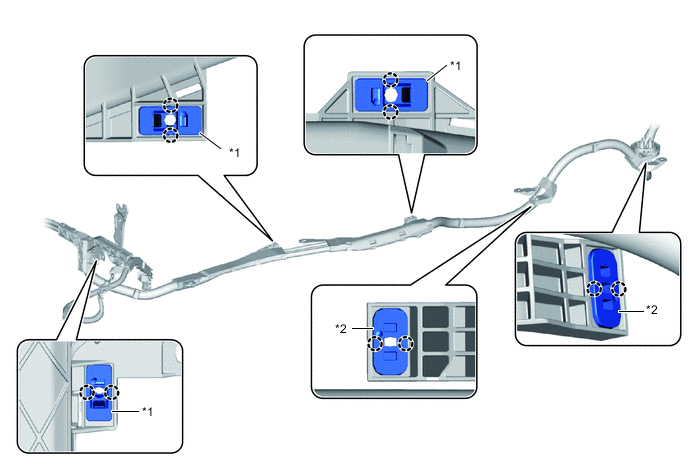
*1 Stud Clamp A *2 Stud Clamp B -
As shown in the illustration, temporarily install 4 new clamps (cable tie type) to the frame wire.
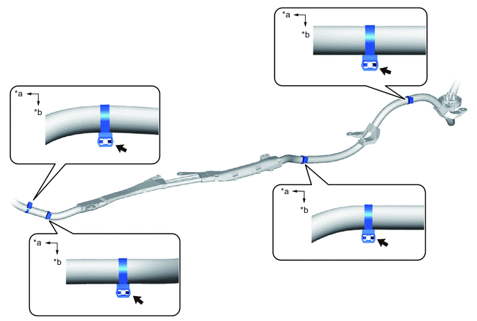
*a Front of the vehicle *b Left side of the vehicle Note
Install with the clamp facing the left side of the vehicle.
Tech Tips
This procedure is only performed when the frame wire will be reused.
-
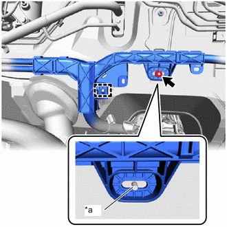
*a Vehicle Side Stud Bolt Portion Engage the clamp and install the frame wire to the vehicle.
Note
When installing, align the vehicle side stud with the hole of the frame wire and install.
-
Temporarily install the nut.
Tech Tips
Fully tighten the nut after the frame wire has been connected under the vehicle floor.
-
Engage the 8 clamps and connect the frame wire to the vehicle.
Note
When installing, align the vehicle side stud with the hole of the frame wire and install.
-
Tighten the clamps (cable tie type) to secure them in place.
-
Install the nut.
- Torque:
- 8.4 N*m { 86 kgf*cm, 74 in.*lbf }
-
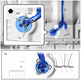
*a Passenger Compartment Side *b Grommet Arrow Portion 
Front of the vehicle Insert the frame wire into the floor panel hole and engage the 3 claws.
Note
Align the arrow of the frame wire grommet with the position shown in the illustration and intall it.
-
Install the front floor center brace to the vehicle with the 2 bolts.
- Torque:
- 45 N*m { 459 kgf*cm, 33 ft.*lbf }
-
-
INSTALL FRONT SUSPENSION CROSSMEMBER SUB-ASSEMBLY
-
INSTALL FC STACK ASSEMBLY
-
INSTALL HYDROGEN TANK UNIT
-
CONNECT FRAME WIRE
CAUTION:
Wear insulated gloves.
-
Motor room side:
-
Fully tighten the nut.
- Torque:
- 8.4 N*m { 86 kgf*cm, 74 in.*lbf }
-
Engage the 2 clamps and connect the motor room frame wire to the frame wire protector of frame wire.
-
Engage the 2 clamps and connect the frame wire to the vehicle.
-
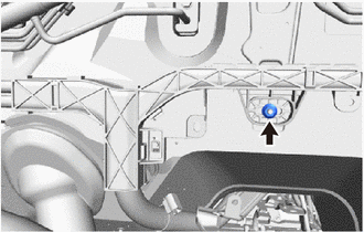
Install the bolt.
- Torque:
- 8.4 N*m { 86 kgf*cm, 74 in.*lbf }
-
Engage the 2 clamps and connect the motor room frame wire to the frame wire protector of frame wire.
-
Engage the clamp and connect the frame wire to the vehicle.
-
Install the bolt and connect the frame wire to the motor room relay block.
- Torque:
- 8.4 N*m { 86 kgf*cm, 74 in.*lbf }
Note
Do not touch the connector terminals.
-
Engage the clamp and connect the No. 2 motor compartment wire to the frame wire.
-
Engage the 2 claws and install the No. 1 relay block cover.
-
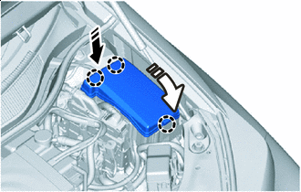

Install in this Direction (1) 
Install in this Direction (2) As shown in the illustration Engage the claw and install the No. 1 relay block cover.
-
Engage the clamp and connect the frame wire to the vehicle.
-
Install the bolt and connect the frame wire to the No. 3 cross member frame bracket sub-assembly RH.
- Torque:
- 8.4 N*m { 86 kgf*cm, 74 in.*lbf }
-
To prevent contamination by foreign matter or water droplets, cover the openings of the inverter with converter assembly with protective tape.
-
*1 Interlock Connector Temporarily install the frame wire to the FC inverter input junction cover with the 4 bolts.
Note
-
Do not touch the rubber seal or terminal portion of the frame wire.
-
Do not scratch or damage the inverter with converter assembly with the terminal portion of the FC inverter input junction cover.
-
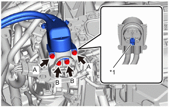
Securely connect the interlock connector.
HINT Item Bolt Head Shape A Flange Bolt B Bolt with Washer -
-
Using an insulated tool, temporarily install the bolts A with the 2 bolts.
- Torque:
- 8.0 N*m { 82 kgf*cm, 71 in.*lbf }
-
Using an insulated tool, temporarily install the bolts B with the 2 bolts.
- Torque:
- 8.0 N*m { 82 kgf*cm, 71 in.*lbf }
-
Using an insulated tool, install the FC inverter input junction cover to the FC inverter input junction assembly.
- Torque:
- 8.0 N*m { 82 kgf*cm, 71 in.*lbf }
Note
-
Do not touch the rubber seal of the FC inverter input junction cover.
-
Securely connect the interlock connector.
-
Engage the clamp and connect the wire harness to the FC inverter input junction cover connector.
-
Connect the FC inverter input junction cover connector.
-
-
Passenger Compartment Side:
-
Engage the 4 clamps and connect the frame wire to the vehicle.
-
Connect the 2 frame wire connectors.
Note
Do not touch the connector terminals.
-
Connect the shielded wire ground of the frame wire.
-
Install the No. 4 EV battery shield panel to the EV battery with the bolt, 2 nuts.
- Torque:
- 7.5 N*m { 76 kgf*cm, 66 in.*lbf }
-
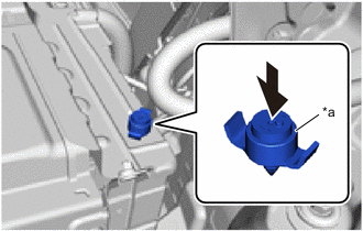
*a Button Push Install the battery cover lock striker to the No. 4 hybrid battery shield panel, then push the button to lock it.
Note
Secure the button by firmly pushing it in until a clicking sound is heard
-
-
Engage the clamp and connect the frame wire to the vehicle.
-
Install the nut and connect frame wire to the fusible link block assembly.
- Torque:
- 6.5 N*m { 66 kgf*cm, 58 in.*lbf }
Note
Do not touch the connector terminals.
-
Engage the 5 claws and install the battery terminal connector cover to the fusible link block assembly.
-
-
INSTALL CHILD RESTRAINT SEAT ANCHOR BRACKET
-
INSTALL INVERTER COVER
-
INSTALL FC STACK SERVICE PLUG GRIP
-
INSTALL SERVICE PLUG GRIP (for EV)