RADIATOR INSTALLATION
PROCEDURE
-
INSTALL RADIATOR ASSEMBLY
-
Install the No. 2 radiator support sub-assembly to the radiator assembly with the 2 bolts.
- Torque:
- 7.0 N*m { 71 kgf*cm, 62 in.*lbf }
-
Install the radiator support sub-assembly to the radiator assembly with the 2 bolts.
- Torque:
- 7.0 N*m { 71 kgf*cm, 62 in.*lbf }
-
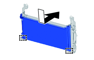
Engage the 2 guides in the direction shown by the arrow in the illustration, and temporarily install the cooler condenser assembly to the radiator support sub-assembly and No. 2 radiator support sub-assembly.
Note
During installation, make sure not to damage the radiator assembly or cooler condenser assembly.
-
Install the cooler condenser assembly to the radiator support sub-assembly and No. 2 radiator support sub-assembly with the 4 bolts.
- Torque:
- 7.0 N*m { 71 kgf*cm, 62 in.*lbf }
-
Using the 6 bolts, install the radiator support sub-assembly and No. 2 radiator support sub-assembly together with the radiator assembly and cooler condenser assembly, as a single unit, to the FC radiator assembly.
Note
During installation, make sure not to damage the radiator assembly, cooler condenser assembly or FC radiator assembly.
-
-
CONNECT NO. 1 EV RADIATOR INLET HOSE
-
To prevent contamination by foreign matter or water droplets, remove the plastic bag from the No. 1 EV radiator inlet hose and radiator assembly immediately before performing the procedure.
-
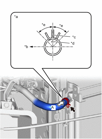
*a View A *b Top of Vehicle *c Radiator Assembly Rib *d Hose paint mark (yellow) *e Claw should be within this range (45°) Connect the No. 1 EV radiator inlet hose to the radiator assembly and slide the hose clip to secure it.
Note
Align the hose and hose clamp at the locations shown in the illustration and install them.
-
-
CONNECT EV RADIATOR OUTLET HOSE
-
To prevent contamination by foreign matter or water droplets, remove the plastic bag from the EV radiator outlet hose and radiator assembly immediately before performing the procedure.
-
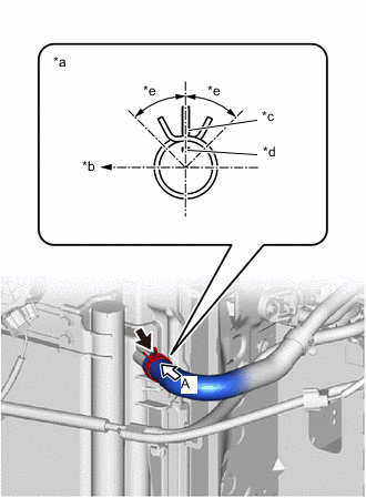
*a View A *b Front of Vehicle *c Radiator Assembly Rib *d Hose paint mark (white) *e Claw should be within this range (45°) Connect the EV radiator outlet hose to the radiator assembly and slide the hose clip to secure it.
Note
Align the hose and hose clamp at the locations shown in the illustration and install them.
-
-
CONNECT AIR CONDITIONER TUBE AND ACCESSORY ASSEMBLY
-
CONNECT DISCHARGE TUBE SUB-ASSEMBLY
-
INSTALL COOL AIR INTAKE DUCT RETAINER SUB-ASSEMBLY
-
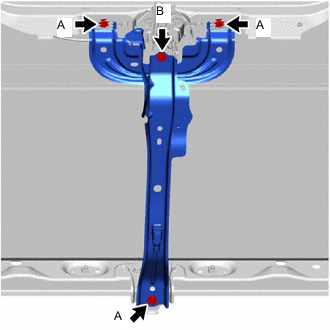
Temporarily install the cool air intake duct retainer sub-assembly to the vehicle with the 4 bolts.
-
Fully tighten 3 bolts A.
- Torque:
- 12.5 N*m { 127 kgf*cm, 9 ft.*lbf }
-
Fully tighten bolt B.
- Torque:
- 8.0 N*m { 82 kgf*cm, 71 in.*lbf }
-
Engage the 2 clamps to connect the hood courtesy switch connector (hood lock assembly).
-
Connect the hood courtesy switch connector (hood lock assembly).
-
Connect the high pitched horn assembly connector.
-
Connect the low pitched horn assembly connector.
-
Connect the ambient temperature sensor connector.
-
-
INSTALL MILLIMETER WAVE RADAR SENSOR ASSEMBLY
-
INSTALL NO. 1 RADIATOR AIR GUIDE LH
-
INSTALL NO. 1 RADIATOR AIR GUIDE RH
-
INSTALL FRONT BUMPER REINFORCEMENT SUB-ASSEMBLY
-
INSTALL FRONT BUMPER ENERGY ABSORBER
-
INSTALL FRONT BUMPER COVER
-
ADD INVERTER COOLANT
-
CHARGE AIR CONDITIONING SYSTEM WITH REFRIGERANT
-
WARM UP COMPRESSOR
-
INSPECT INVERTER COOLANT
-
INSPECT FOR REFRIGERANT LEAK
-
INSTALL NO. 3 RADIATOR AIR GUIDE
-
INSTALL FRONT BUMPER ABSORBER LOWER