NAME PLATE INSTALLATION
PROCEDURE
-
INSTALL NO. 2 TAIL GATE MARK
Tech Tips
When installing the No. 2 tail gate mark, heat the vehicle body and No. 2 tail gate mark using a heat light.
Standard Item Temperature Vehicle Body 40 to 60°C (104 to 140°F) No. 2 Tail Gate Mark 20 to 30°C (68 to 86°F)
-
Clean the vehicle body surface.
-
Using a heat light, heat the vehicle body surface.
-
Remove the double-sided tape from the vehicle body.
-
Wipe off any tape adhesive residue with cleaner.
-
-
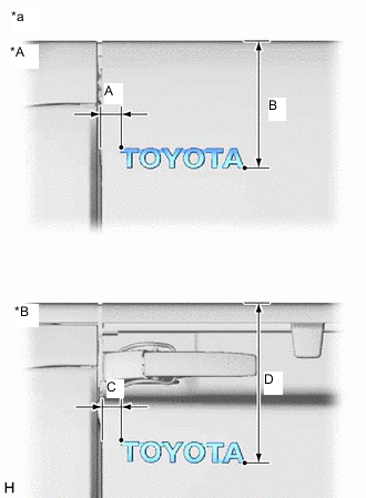
*A for A Deck *B for J Deck *a Reference Values Install a new No. 2 tail gate mark.
-
Using a heat light, heat the vehicle body and a new No. 2 tail gate mark.
-
Remove the peeling paper from the face of the No. 2 tail gate mark.
Tech Tips
After removing the peeling paper, keep the exposed adhesive free from foreign matter.
-
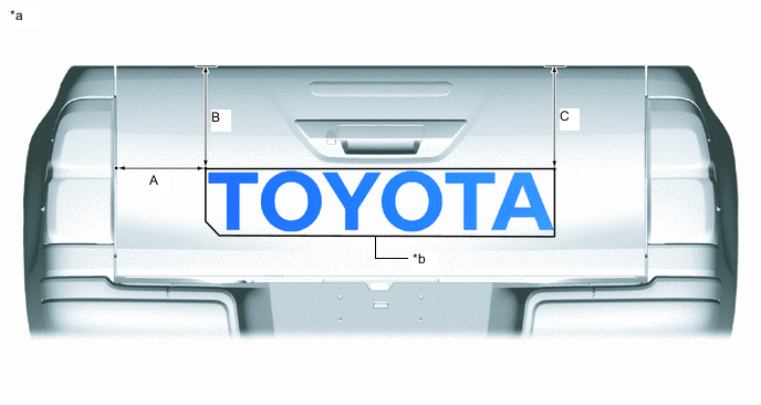
Install the No. 2 tail gate mark in the position shown in the illustration.
Tech Tips
-
The values in the illustration are reference values.
-
Press the No. 2 tail gate mark firmly to install it.
Standard Area Specified Condition A 24.8 mm (0.976 in.) B 165.7 mm (6.52 in.) C 24.5 mm (0.965 in.) D 213.3 mm (8.398 in.) -
-
-
-
INSTALL REAR NAME PLATE
Tech Tips
When installing the rear name plate, heat the vehicle body and rear name plate using a heat light.
Standard Item Temperature Vehicle Body 40 to 60°C (104 to 140°F) Rear Name Plate 20 to 30°C (68 to 86°F)
-
Clean the vehicle body surface.
-
Using a heat light, heat the vehicle body surface.
-
Remove the double-sided tape from the vehicle body.
-
Wipe off any tape adhesive residue with cleaner.
-
-
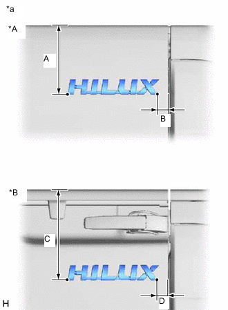
*A for A Deck *B for J Deck *a Reference Values Install a new rear name plate.
-
Using a heat light, heat the vehicle body and a new rear name plate.
-
Remove the peeling paper from the face of the rear name plate.
Tech Tips
After removing the peeling paper, keep the exposed adhesive free from foreign matter.
-
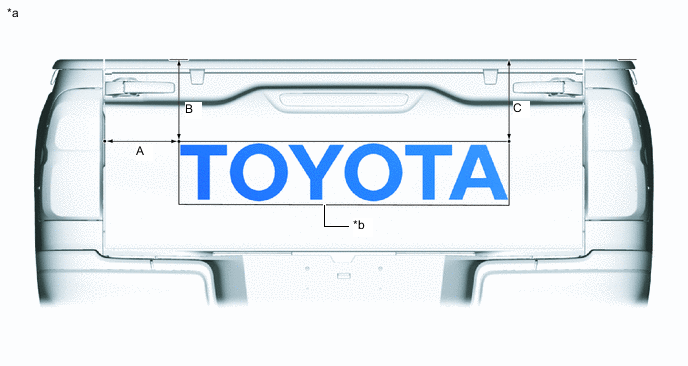
Install the rear name plate in the position shown in the illustration.
Tech Tips
-
The values in the illustration are reference values.
-
Press the rear name plate firmly to install it.
Standard Area Specified Condition A 165.6 mm (6.52 in.) B 26.5 mm (1.044 in.) C 221.2 mm (8.709 in.) D 26.4 mm (1.039 in.) -
-
-
-
INSTALL TAIL GATE MARK
Tech Tips
When installing the tail gate mark, heat the vehicle body and tail gate mark using a heat light.
Standard Item Temperature Vehicle Body 40 to 60°C (104 to 140°F) Tail Gate Mark 20 to 30°C (68 to 86°F)
-
Clean the vehicle body surface.
-
Using a heat light, heat the vehicle body surface.
-
Remove the double-sided tape from the vehicle body.
-
Wipe off any tape adhesive residue with cleaner.
-
-
Install a new tail gate mark.
-
Using a heat light, heat the vehicle body and a new tail gate mark.
-
Remove the peeling paper from the face of the tail gate mark.
Tech Tips
After removing the peeling paper, keep the exposed adhesive free from foreign matter.
-
for A Deck:
Install the tail gate mark in the position shown in the illustration.
Tech Tips
-
The values in the illustration are reference values.
-
Press the tail gate mark firmly to install it.
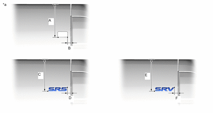
*a Reference Values - - Standard Area Specified Condition Area Specified Condition A 222.1 mm (8.74 in.) B 22.5 mm (0.886 in.) C 210 mm (8.27 in.) D 22.6 mm (0.89 in.) E 210.2 mm (8.28 in.) F 22.6 mm (0.89 in.) -
-
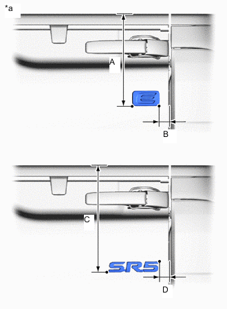
*a Reference Values for J Deck:
Install the tail gate mark in the position shown in the illustration.
Tech Tips
-
The values in the illustration are reference values.
-
Press the tail gate mark firmly to install it.
Standard Area Specified Condition A 269.9 mm (10.6 in.) B 22.8 mm (0.898 in.) C 269.9 mm (10.6 in.) D 22.8 mm (0.898 in.) -
-
-
-
INSTALL NO. 3 TAIL GATE MARK
Tech Tips
When installing the No. 3 tail gate mark, heat the vehicle body and No. 3 tail gate mark using a heat light.
Standard Item Temperature Vehicle Body 40 to 60°C (104 to 140°F) No. 3 Tail Gate Mark 20 to 30°C (68 to 86°F) CAUTION:
-
Do not touch the heat light and heated parts.
-
Touching the heat light may result in burns.
-
Touching heated parts for a long time may result in burns.
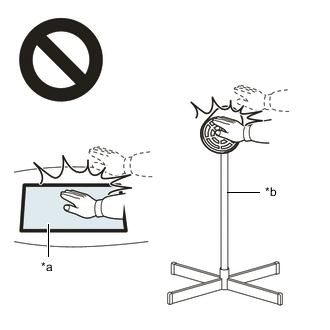
*a Heated Part *b Heat Light
-
Clean the vehicle body surface.
-
Using a heat light, heat the vehicle body surface.
-
Remove the double-sided tape from the vehicle body.
-
Wipe off any tape adhesive residue with cleaner.
-
-
Installation temperature.
-
When the ambient temperature is below 15°C (59°F), perform the installation procedure after warming the vehicle body surface (installation surface of the door frame, etc.) and tape to between 20 and 30°C (68 and 86°F) using a heat light. When the ambient temperature is higher than 35°C (95°F), cool the vehicle body surface (installation surface of the door frame, etc.) and tape to between 20 and 30°C (68 and 86°F) prior to installation.
Tech Tips
-
The most appropriate temperature for installing the tape is 25°C (77°F).
-
When the temperature is low, the tape turns stiff and falls off easily. When the temperature is high, the tape loses elasticity.
-
-
-
Before installation.
-
Make sure any dirt on and around the vehicle body surface where the tape will be installed (installation surface of the door frame, etc.) is removed, and that the surface is smooth. If the surface is rough or dirt remains when pressing the tape onto the surface, air will be trapped under the tape and result in a poor appearance.
Tech Tips
Spray water on the shop floor to settle any dust.
-
-
Key points for handling the tape.
-
The tape bends and rolls up easily. Store the tape between flat pieces of cardboard or other similar objects and keep it dry and level.
Note
Do not bend the tape or leave it in a place with a high temperature.
-
-
Key points for the installation of the tape (how to use a squeegee and the installation procedure for a flat surface).
Note
-
Position the tape with a high level of accuracy to achieve a neat finish and to avoid peeling.
-
The tape cannot be reused because it deforms and will not fit after removal.
-
To avoid air bubbles, slightly raise the part of the tape that is going to be applied so that its adhesive surface does not touch the vehicle body while applying the tape. Tilt the squeegee 40 to 50° (for pressing forward) or 30 to 45° (for pulling) from the vehicle body surface and press with a force of 20 to 30 N (2 to 3 kgf) while moving the squeegee at a constant slow speed of 3 to 7 cm (1.2 to 2.8 in.) per second.
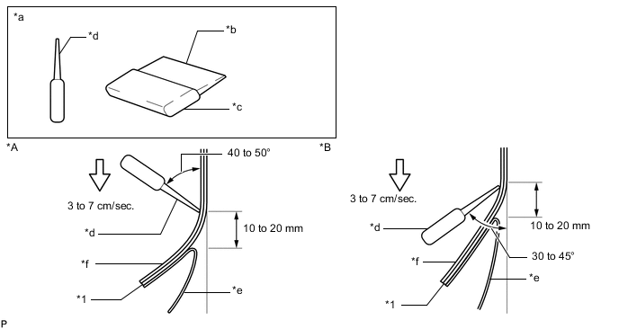
*A Pressing *B Pulling *1 No. 3 tail gate mark - - *a Sectional View *b Non-padded Side *c Padded Side *d Squeegee *e Release Paper *f Application Sheet Note
Be sure to observe the specified pressing speed, force and angle of the squeegee to avoid wrinkles and air bubbles.
Tech Tips
-
Either angle of the squeegee (for pressing forward or for pulling) is acceptable.
-
Be sure to apply the tape while removing the release paper 10 to 20 mm (0.393 to 0.787 in.) from the edge of the squeegee.
-
-
-
Key points for the installation of the tape (how to use a squeegee and the installation procedure for corners).
-
Remove the release paper and apply the tape carefully with your fingers.
-
Before applying the tape to each corner, heat the tape using a heat light and gradually apply it to avoid wrinkles in the tape and achieve a neat finish.
-
-
Check after installation.
-
After completing the application, check if the tape is applied neatly. If the tape is not applied neatly, apply new tape.
Note
Do not reuse the tape.
-
-
Install a new No. 3 tail gate mark.
-
Using a heat light, heat the vehicle body and a new No. 3 tail gate mark.
-
Remove the peeling paper from the face of the No. 3 tail gate mark.
-
for A Deck:
-
Align the application tape with the top of tail gate and using a squeegee, apply the No. 3 tail gate mark.
-
Remove the application sheet.
*a Reference Values *b Application Sheet Standard Area Specified Condition Area Specified Condition A 236.8 mm (9.32 in.) B 269.9 mm (10.6 in.) C 269.9 mm (10.6 in.) - - -
-
for J Deck:
-
Align the application tape with the top of tail gate and using a squeegee, apply the No. 3 tail gate mark.
-
Remove the application sheet.
*a Reference Values *b Application Sheet Standard Area Specified Condition Area Specified Condition A 214.3 mm (8.44 in.) B 237.5 mm (9.35 in.) C 237.5 mm (9.35 in.) - - -
-
-
-
INSTALL FRONT DOOR NAME PLATE
Tech Tips
When installing the front door name plate, heat the vehicle body and front door name plate using a heat light.
Standard Item Temperature Vehicle Body 40 to 60°C (104 to 140°F) Front Door Name Plate 20 to 30°C (68 to 86°F)
-
Clean the vehicle body surface.
-
Using a heat light, heat the vehicle body surface.
-
Remove the double-sided tape from the vehicle body.
-
Wipe off any tape adhesive residue with cleaner.
-
-
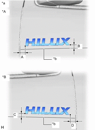
*A for LH Side *B for RH Side *a Reference Values *b Edge of Curved Surface Install a new front door name plate.
-
Using a heat light, heat the vehicle body and a new front door name plate.
-
Remove the peeling paper from the face of the front door name plate.
Tech Tips
After removing the peeling paper, keep the exposed adhesive free from foreign matter.
-
Install the front door name plate in the position shown in the illustration.
Tech Tips
-
The values in the illustration are reference values.
-
Press the front door name plate firmly to install it.
Standard Area Specified Condition A 25.4 mm (1.0 in.) B 13.8 mm (0.543 in.) C 13.8 mm (0.543 in.) D 26.7 mm (1.051 in.) -
-
-
-
INSTALL FRONT DOOR NO. 2 NAME PLATE
Tech Tips
When installing the front door No. 2 name plate, heat the vehicle body and front door No. 2 name plate using a heat light.
Standard Item Temperature Vehicle Body 40 to 60°C (104 to 140°F) Front Door No. 2 Name Plate 20 to 30°C (68 to 86°F)
-
Clean the vehicle body surface.
-
Using a heat light, heat the vehicle body surface.
-
Remove the double-sided tape from the vehicle body.
-
Wipe off any tape adhesive residue with cleaner.
-
-
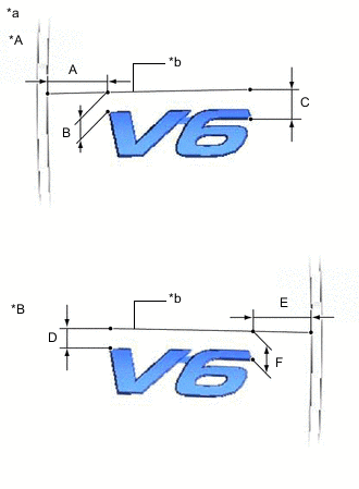
*A for LH Side *B for RH Side *a Reference Values *b Edge of Curved Surface Install a new front door No. 2 name plate.
-
Using a heat light, heat the vehicle body and a new front door No. 2 name plate.
-
Remove the peeling paper from the face of the front door No. 2 name plate.
Tech Tips
After removing the peeling paper, keep the exposed adhesive free from foreign matter.
-
Install the front door No. 2 name plate in the position shown in the illustration.
Tech Tips
-
The values in the illustration are reference values.
-
Press the front door No. 2 name plate firmly to install it.
Standard Area Specified Condition A 31.7 mm (1.25 in.) B 9.6 mm (0.378 in.) C 14.7 mm (0.579 in.) D 9.6 mm (0.378 in.) E 40.6 mm (1.60 in.) F 14.6 mm (0.575 in.) -
-
-