FRONT BUMPER(for Steel Type Bumper) REASSEMBLY
PROCEDURE
-
INSTALL FOG LIGHT COVER LH (w/ Fog Light)
-
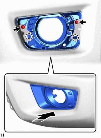

Install in this Direction Attach the claw to install the fog light cover LH as shown in the illustration.
-
Install the 2 screws.
-
-
INSTALL FOG LIGHT COVER RH (w/ Fog Light)
Tech Tips
Use the same procedure described for the LH side.
-
INSTALL FRONT BUMPER HOLE COVER LH (w/o Fog Light)
-
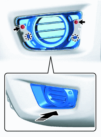
Install in this Direction Attach the claw to install the front bumper hole cover LH as shown in the illustration.
-
Install the 2 screws.
-
-
INSTALL FRONT BUMPER HOLE COVER RH (w/o Fog Light)
Tech Tips
Use the same procedure described for the LH side.
-
INSTALL FOG LIGHT ASSEMBLY LH (w/ Fog Light)
-
INSTALL FOG LIGHT ASSEMBLY RH (w/ Fog Light)
Tech Tips
Use the same procedure described for the LH side.
-
INSTALL FRONT CENTER BUMPER SUB-ASSEMBLY
-
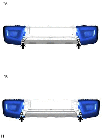
Install the front center bumper sub-assembly with the 3 nuts as shown in the illustration.
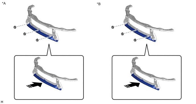
*A for Standard Body *B for Wide Body Install in this Direction - - - Torque:
- 5.5 N*m { 56 kgf*cm, 49 in.*lbf }
-
-
INSTALL FRONT BUMPER EXTENSION LH
-
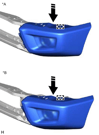
*A for Standard Body *B for Wide Body Install in this Direction Attach the guide to install the front bumper extension LH as shown in the illustration.
-
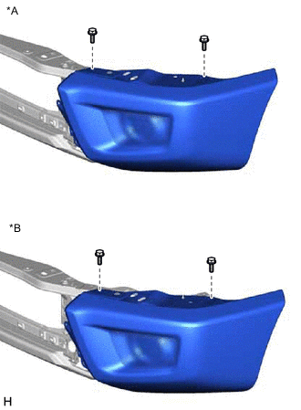
*A for Standard Body *B for Wide Body Install the 2 bolts.
- Torque:
- 8.0 N*m { 82 kgf*cm, 71 in.*lbf }
-
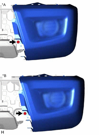
*A for Standard Body *B for Wide Body Install the bolt.
- Torque:
- 8.0 N*m { 82 kgf*cm, 71 in.*lbf }
-
*A for Standard Body *B for Wide Body Install the 2 bolts.
- Torque:
- 8.0 N*m { 82 kgf*cm, 71 in.*lbf }
-
-
INSTALL FRONT BUMPER EXTENSION RH
Tech Tips
Use the same procedure described for the LH side.
-
INSTALL FRONT VALANCE PANEL SUB-ASSEMBLY
-
Attach the clip to install the front valance panel sub-assembly as shown in the illustration.
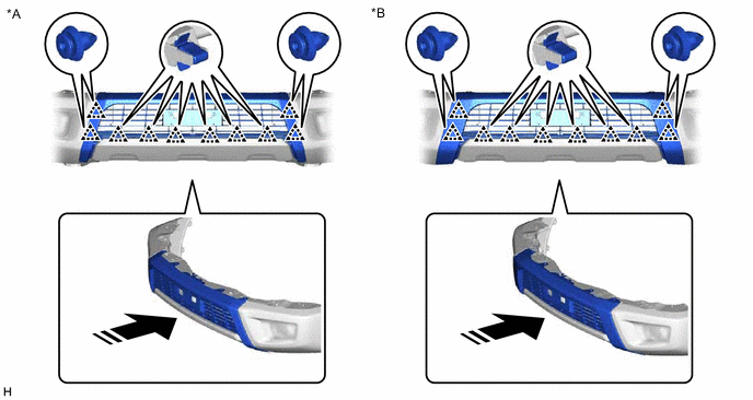
*A for Standard Body *B for Wide Body Install in this Direction - - -
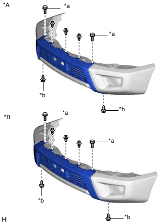
*A for Standard Body *B for Wide Body *a Bolt *b Screw Install the 2 bolts.
- Torque:
- 5.5 N*m { 56 kgf*cm, 49 in.*lbf }
-
Install the 2 screws and 3 clips.
-
-
INSTALL RADIATOR GRILLE