| DTC Code | DTC Name |
|---|---|
| B2430 | LED Headlight LH |
| B2431 | LED Headlight RH |
DESCRIPTION
The illumination of the low beam headlights is controlled by the body ECU. When the headlights are turned on, the headlight leveling ECU assembly receives a signal from the headlight assembly and detects the illumination condition of the low beam headlights.
| DTC No. | Detection Item | DTC Detection Condition | Trouble Area |
|---|---|---|---|
| B2430 | LED Headlight LH | Low beam headlight LH malfunction |
|
| B2431 | LED Headlight RH | Low beam headlight RH malfunction |
|
DTC B2430 and B2431 are not output if 12 seconds have not elapsed since the ignition switch was turned to ON.
CAUTION / NOTICE / HINT
-
Inspect the fuses for circuits related to this system before performing the following procedure.
-
If the headlight leveling ECU assembly has been replaced, it is necessary to initialize the headlight leveling ECU assembly.
-
When replacing the headlight leveling ECU assembly, be sure to initialize the automatic light control system.
-
As the door control battery is installed between the vehicle battery and body ECU, first perform the inspections to confirm that there are no malfunctions in the power source circuit for the body ECU before performing this troubleshooting procedure.*
*: w/ Power Door Lock
-
If DTC B2416 and/or B241A (Automatic Headlight Beam Level Control System) is output at the same time as DTC B2430 and/or B2431, perform troubleshooting for DTC B2416 and/or B241A (Automatic Headlight Beam Level Control System) first.
-
The light system (exterior) uses the CAN communication system. First perform the communication function checks in "How to Proceed with Troubleshooting" to confirm that there are no communication malfunctions before proceeding with troubleshooting.
PROCEDURE
- Click here
CLEAR DTC
-
Clear the DTCs.
- Body Electrical > HL AutoLeveling > Clear DTCs
-
-
Result Proceed to NEXT
- NEXTClick here
-
- Click here
CHECK FOR DTC
-
Check for DTCs.
- Body Electrical > HL AutoLeveling > Trouble Codes
-
-
Result Result Proceed to Both DTC B2430 and B2431 are not output. A Both DTC B2430 and B2431 are output. B Only DTC B2430 or B2431 is output. C
- A
USE SIMULATION METHOD TO CHECKClick here
- BClick here
- CClick here
-
- Click here
INSPECT HEADLIGHT RELAY (H-LP)
-
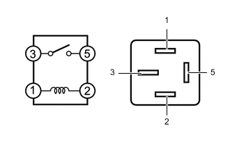
Remove the headlight relay (H-LP) from the engine room relay block assembly.
-
Measure the resistance according to the value(s) in the table below.
Standard Resistance Tester Connection Condition Specified Condition 3 - 5 Battery voltage not applied between terminals 1 and 2 10 kΩ or higher 3 - 5 Battery voltage applied between terminals 1 and 2 Below 1 Ω Result Proceed to OK NG
- OKClick here
- NG
REPLACE HEADLIGHT RELAY (H-LP)
-
- Click here
CHECK HARNESS AND CONNECTOR (HEADLIGHT RELAY [H-LP] - BATTERY)
-
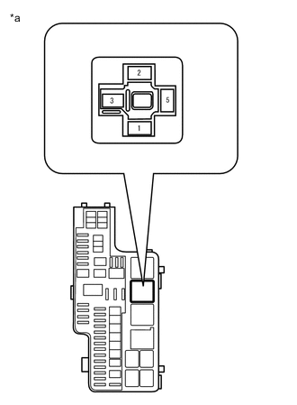
*a Front view of wire harness connector
(to Headlight Relay [H-LP])
Remove the headlight relay (H-LP) from the engine room relay block assembly.
-
Measure the voltage according to the value(s) in the table below.
Standard Voltage Tester Connection Condition Specified Condition Headlight relay (H-LP) terminal 3 - Body ground Always 11 to 14 V Headlight relay (H-LP) terminal 1 - Body ground Always 11 to 14 V Result Proceed to OK NG
- OKClick here
- NG
REPAIR OR REPLACE HARNESS OR CONNECTOR
-
- Click here
CHECK HARNESS AND CONNECTOR (HEADLIGHT RELAY [H-LP] - HEADLIGHT ASSEMBLY)
-
*1: for LH Side
-
*2: for RH Side
-
Remove the headlight relay (H-LP) from the engine room relay block assembly.
-
Disconnect the A18*1 or A17*2 headlight assembly connector.
-
Measure the resistance according to the value(s) in the table below.
Standard Resistance Tester Connection Condition Specified Condition Headlight relay (H-LP) terminal 5 - A18-4 (LO)*1 Always Below 1 Ω Headlight relay (H-LP) terminal 5 - A17-4 (LO)*2 Always Below 1 Ω Headlight relay (H-LP) terminal 5 - Body ground Always 10 kΩ or higher Result Proceed to OK NG
- OKClick here
- NG
REPAIR OR REPLACE HARNESS OR CONNECTOR
-
- Click here
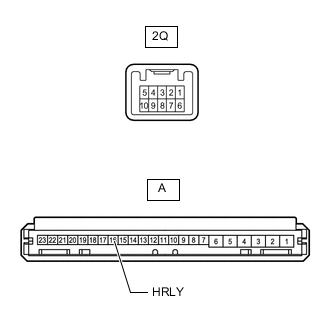
CHECK HARNESS AND CONNECTOR (HEADLIGHT RELAY [H-LP] - INSTRUMENT PANEL JUNCTION BLOCK ASSEMBLY)
-
Remove the headlight relay (H-LP) from the engine room relay block assembly.
-
Disconnect the 2Q instrument panel junction block assembly connector.
-
Measure the resistance according to the value(s) in the table below.
Standard Resistance Tester Connection Condition Specified Condition Headlight relay (H-LP) terminal 2 - 2Q-4 Always Below 1 Ω Headlight relay (H-LP) terminal 2 - 2Q-4 Always 10 kΩ or higher Result Proceed to OK NG
- OKClick here
- NG
REPAIR OR REPLACE HARNESS OR CONNECTOR
-
- Click here
INSPECT INSTRUMENT PANEL JUNCTION BLOCK ASSEMBLY
-
Remove the instrument panel junction block assembly.
for LHD:
for RHD:
-
Remove the body ECU from the instrument panel junction block assembly.
for LHD:
for RHD:
-
Measure the resistance according to the value(s) in the table below.
Standard Resistance Tester Connection Condition Specified Condition A-16 (HRLY) - 2Q-4 Always Below 1 Ω Result Result OK NG
- OKClick here
- NG
REPLACE INSTRUMENT PANEL JUNCTION BLOCK ASSEMBLY for LHD:
REPLACE INSTRUMENT PANEL JUNCTION BLOCK ASSEMBLYClick here
REPLACE INSTRUMENT PANEL JUNCTION BLOCK ASSEMBLY for RHD:
REPLACE INSTRUMENT PANEL JUNCTION BLOCK ASSEMBLYClick here
-
- Click here
CHECK BODY ECU
-
*1: for LH Side
-
*2: for RH Side
-
Disconnect the A18*1 or A17*2 headlight assembly connector.
-
Measure the voltage according to the value(s) in the table below.
Standard Voltage Table 1. for LH Side Tester Connection Condition Specified Condition A18-4 (LO) - Body ground Headlight dimmer switch (light control switch) in head position 11 to 14 V Table 2. for RH Side Tester Connection Condition Specified Condition A17-4 (LO) - Body ground Headlight dimmer switch (light control switch) in head position 11 to 14 V Result Proceed to OK NG
- OK
REPLACE HEADLIGHT LEVELING ECU ASSEMBLYClick here
- NG
REPLACE BODY ECU for LHD:
REPLACE BODY ECUClick here
REPLACE BODY ECU for RHD:
REPLACE BODY ECUClick here
-
- Click here
CHECK HARNESS AND CONNECTOR (HEADLIGHT RELAY [H-LP] - HEADLIGHT ASSEMBLY)
-
Remove the headlight relay (H-LP) from the engine room relay block assembly.
-
Disconnect the A18*1 or A17*2 headlight assembly connector.
-
*1: for LH Side
-
*2: for RH Side
-
-
Measure the resistance according to the value(s) in the table below.
Standard Resistance Table 3. for LH Side (B2430) Tester Connection Condition Specified Condition Headlight relay (H-LP) terminal 5 - A18-4 (LO) Always Below 1 Ω Headlight relay (H-LP) terminal 5 - Body ground Always 10 kΩ or higher Table 4. for RH Side (B2431) Tester Connection Condition Specified Condition Headlight relay (H-LP) terminal 5 - A17-4 (LO) Always Below 1 Ω Headlight relay (H-LP) terminal 5 - Body ground Always 10 kΩ or higher Result Proceed to OK NG
- OKClick here
- NG
REPAIR OR REPLACE HARNESS OR CONNECTOR
-
- Click here
CHECK HARNESS AND CONNECTOR (HEADLIGHT ASSEMBLY - HEADLIGHT LEVELING ECU ASSEMBLY AND BODY GROUND)
-
Disconnect the A18*1 or A17*2 headlight assembly connector.
-
*1: for LH Side
-
*2: for RH Side
-
-
Disconnect the G80 headlight leveling ECU assembly connector.
-
Measure the resistance according to the value(s) in the table below.
Standard Resistance Table 5. for LH Side (B2430) Tester Connection Condition Specified Condition A18-6 (S) - G80-3 (LLEW) Always Below 1 Ω A18-5 (E) - Body ground Always Below 1 Ω A18-6 (S) - Body ground Always 10 kΩ or higher Table 6. for RH Side (B2431) Tester Connection Condition Specified Condition A17-6 (S) - G80-2 (RLEW) Always Below 1 Ω A17-5 (E) - Body ground Always Below 1 Ω A17-6 (S) - Body ground Always 10 kΩ or higher Result Proceed to OK NG
- OKClick here
- NG
REPAIR OR REPLACE HARNESS OR CONNECTOR
-
- Click here
CHECK HEADLIGHT ASSEMBLY
-
Temporarily replace the headlight assembly with a new or normally functioning one.
-
Check for DTCs.
- Body Electrical > HL AutoLeveling > Trouble Codes
-
-
Result Result Proceed to Both DTC B2430 and B2431 are not output. A Only DTC B2430 or B2431 is output. B
- A
END (HEADLIGHT ASSEMBLY WAS DEFECTIVE)
- B
REPLACE HEADLIGHT LEVELING ECU ASSEMBLYClick here
-