LIGHTING SYSTEM TERMINALS OF ECU
-
CHECK INSTRUMENT PANEL JUNCTION BLOCK ASSEMBLY, BODY ECU (w/ Automatic Light Control System)
-
Remove the body ECU from the instrument panel junction block assembly.
for LHD:
for RHD:
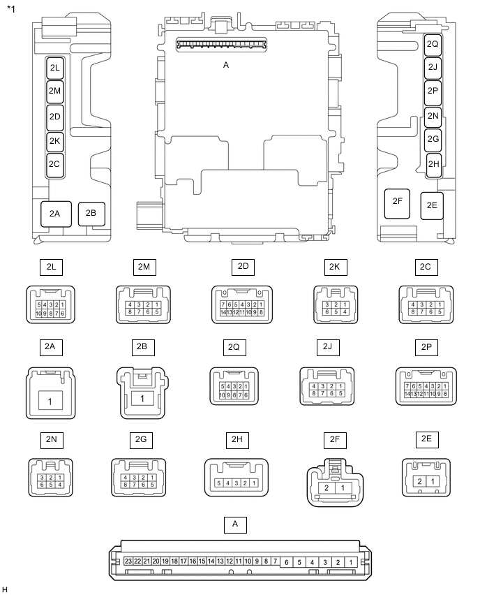
*1 Instrument Panel Junction Block Assembly (for LHD) - - 
*1 Instrument Panel Junction Block Assembly (for RHD) - - 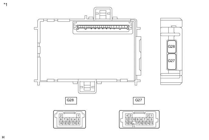
*1 Body ECU - - -
Connect the instrument panel junction block assembly connectors.
-
Measure the voltage and resistance according to the value(s) in the table below.
Terminal No. (Symbol) Wiring Color Terminal Description Condition Specified Condition A-6 (BECU) - Body ground - Battery power supply Always 11 to 14 V A-7 (IG) - Body ground - Ignition power supply Ignition switch off Below 1 V Ignition switch ON 11 to 14 V A-1 (GND) - Body ground - Ground Always Below 1 Ω -
Install the body ECU to the instrument panel junction block assembly.
for LHD:
for RHD:
-
Measure the voltage according to the value(s) in the table below.
Terminal No. (Symbol) Wiring Color Terminal Description Condition Specified Condition G27-1 (TRLY) - Body ground P - Body ground Tail light relay (TAIL) drive output Taillights on Below 2 V Taillights off 11 to 14 V G28-5 (CLTB) - G28-3 (CLTE) W - P Automatic light control sensor power supply output Headlight dimmer switch (light control switch) in AUTO position 11 to 14 V G28-6 (A) - Body ground Y - Body ground Headlight dimmer switch (light control switch) AUTO signal input Headlight dimmer switch (light control switch) not in AUTO position 11 to 14 V Headlight dimmer switch (light control switch) in AUTO position Below 1 V G28-7 (TAIL) - Body ground P - Body ground Headlight dimmer switch (light control switch) tail signal input Headlight dimmer switch (light control switch) in neither tail nor head position 11 to 14 V Headlight dimmer switch (light control switch) in tail or head position Below 1 V G28-8 (HEAD) - Body ground B - Body ground Headlight dimmer switch (light control switch) head signal input Headlight dimmer switch (light control switch) not in head position 11 to 14 V Headlight dimmer switch (light control switch) in head position Below 1 V G28-10 (FFOG) - Body ground* GR - Body ground Front fog light switch input Front fog light switch off 11 to 14 V Front fog light switch on Below 1 V G28-13 (HF) - Body ground V - Body ground Headlight dimmer switch high flash signal input Headlight dimmer switch not in high flash position 11 to 14 V Headlight dimmer switch in high flash position Below 1 V G28-14 (HU) - Body ground SB - Body ground Headlight dimmer switch high signal input Headlight dimmer switch in low position 11 to 14 V Headlight dimmer switch in high position Below 1 V 2P-12 (FFGO) - Body ground* GR - Body ground Front fog light signal output Headlight dimmer switch (light control switch) in tail or head position and front fog light switch off 11 to 14 V Headlight dimmer switch (light control switch) in tail or head position and front fog light switch on Below 1 V 2Q-4 (HRLY) - Body ground V - Body ground Headlight relay (H-LP) drive output Headlight dimmer switch (light control switch) in head position Below 1 V Headlight dimmer switch (light control switch) not in head position 11 to 14 V 2Q-5 (DIM) - Body ground SB - Body ground Headlight dimmer relay (DIMMER) drive output Headlight dimmer switch (dimmer switch) in high or high flash position Below 1 V Headlight dimmer switch (dimmer switch) not in high or high flash position 11 to 14 V *: w/ Front Fog Light
-
Measure the voltage and check the waveform between each connector terminal using an oscilloscope according to the value(s) in the table below.
Terminal No. (Symbol) Wiring Color Terminal Description Condition Specified Condition G28-4 (CLTS) - Body ground LG - Body ground Automatic light control sensor signal input Ignition switch ON, headlight dimmer switch (light control switch) in AUTO position and automatic light control sensor covered with a hand → Automatic light control sensor exposed to ambient light Pulse generation
(waveform varies depending on light volume)
2L-4 (DCTY) - Body ground R - Body ground Driver door courtesy light switch input Driver door open Below 1 V Driver door closed Pulse generation
-
-
CHECK COMBINATION METER ASSEMBLY
-
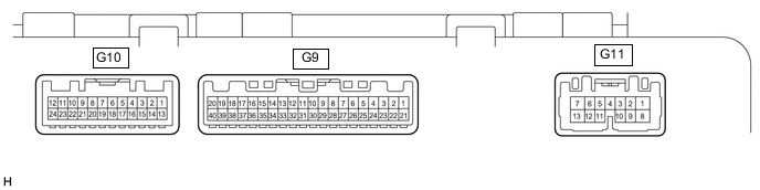
Disconnect the G9, G10 and G11 combination meter assembly connectors.
-
Measure the resistance and voltage according to the value(s) in the table below.
Terminal No. (Symbol) Wiring Color Terminal Description Condition Specified Condition G9-21 (B) - Body ground W - Body ground Battery power supply Always 11 to 14 V G9-22 (IG+) - Body ground Y - Body ground Ignition power supply Ignition switch off Below 1 V Ignition switch ON 11 to 14 V G11-7 (B) - Body ground L - Body ground Battery power supply Always 11 to 14 V G9-27 (EP) - Body ground W-B - Body ground Ground Always Below 1 Ω G10-20 (GND) - Body ground W-B - Body ground Ground Always Below 1 Ω -
Reconnect the G9, G10 and G11 combination meter assembly connectors.
-
Measure the voltage according to the value(s) in the table below.
Terminal No. (Symbol) Wiring Color Terminal Description Condition Specified Condition G11-2 (HAZ) - Body ground SB - Body ground Clock assembly (hazard warning switch) signal input Clock assembly (hazard warning switch) off 11 to 14 V Clock assembly (hazard warning switch) on Below 1 V G11-3 (SW) - Body ground R - Body ground Turn signal switch (full turn position) signal input Ignition switch ON
Turn signal switch off
11 to 14 V Ignition switch ON
Turn signal switch in full turn position
Below 1 V G11-4 (ER) - Body ground P - Body ground Turn signal switch (right turn position) signal input Ignition switch ON
Turn signal switch off
11 to 14 V Ignition switch ON
Turn signal switch in right turn position
Below 1 V G11-5 (EL) - Body ground BE - Body ground Turn signal switch (left turn position) signal input Ignition switch ON
Turn signal switch off
11 to 14 V Ignition switch ON
Turn signal switch in left turn position
Below 1 V G11-8 (LL) - Body ground Y - Body ground LH turn signal light signal output Ignition switch ON
LH turn signal light off
Below 1 V Ignition switch ON
LH turn signal light blinking
Below 1 V ←→ 11 to 14 V G11-13 (LR) - Body ground SB - Body ground RH turn signal light signal output Ignition switch ON
RH turn signal light off
Below 1 V Ignition switch ON
RH turn signal light blinking
Below 1 V ←→ 11 to 14 V G10-1 (FOG) - Body ground*1 P - Body ground Front fog light signal Ignition switch ON, front fog light switch on 11 to 14 V Ignition switch ON, front fog light switch off Below 1 V G10-11 (DRLE) - Body ground*2 G - Body ground Running light relay (DRL) drive output Daytime running light on Below 1 V Daytime running light off 11 to 14 V *1: w/ Fron Fog Light
*2: w/ Daytime Running Light
-
-
CHECK HEADLIGHT LEVELING ECU ASSEMBLY (for LED Headlight)

-
Disconnect the G80 headlight leveling ECU assembly connector.
-
Measure the resistance and voltage according to the value(s) in the table below.
Terminal No. (Symbol) Wiring Color Terminal Description Condition Specified Condition G80-1 (IG) - Body ground G - Body ground Ignition power supply Ignition switch off Below 1 V Ignition switch ON 11 to 14 V G80-9 (E1) - Body ground W-B - Body ground Ground Always Below 1 Ω -
Reconnect the G80 headlight leveling ECU assembly connector.
-
Measure the voltage and check the waveform between each connector terminal using an oscilloscope according to the value(s) in the table below.
Terminal No. (Symbol) Wiring Color Terminal Description Condition Specified Condition G80-2 (RLEW) - Body ground R - Body ground RH side LED headlight signal input Headlight dimmer switch off Below 1 V Headlight dimmer switch (light control switch) in head position Pulse generation G80-3 (LLEW) - Body ground L - Body ground LH side LED headlight signal input Headlight dimmer switch off Below 1 V Headlight dimmer switch (light control switch) in head position Pulse generation
-