WIPER AND WASHER SYSTEM Headlight Cleaner Motor and Relay Circuit
DESCRIPTION
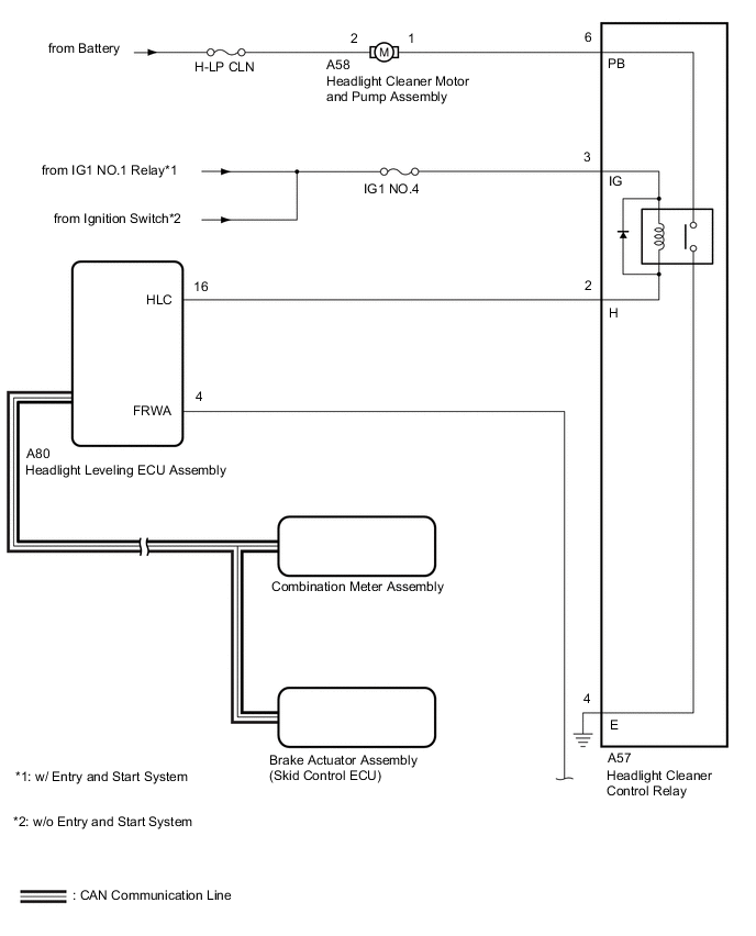
The headlight leveling ECU assembly controls the headlight cleaner motor and pump assembly.
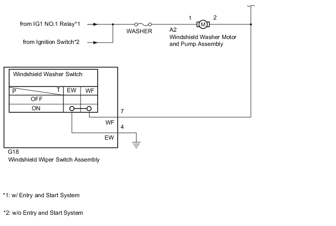
WIRING DIAGRAM
CAUTION / NOTICE / HINT
Note
-
First check that the front washer operates normally.
-
Inspect the fuses and relays for circuits related to this system before performing the following inspection procedure.
-
The headlight cleaner system uses the CAN communication system. Inspect the communication function by following How to Proceed with Troubleshooting. Troubleshoot the window defogger system after confirming that the communication system is functioning properly.
-
w/ Automatic Headlight Beam Level Control System:
If the headlight leveling ECU assembly has been replaced, it is necessary to initialize the headlight leveling ECU assembly.
PROCEDURE
-
CHECK FOR DTC
-
Clear the DTCs.
Body Electrical > HL AutoLeveling > Clear DTCs -
Check for DTCs.
Body Electrical > HL AutoLeveling > Trouble CodesOK DTC is not output. Result Result Proceed to OK A NG (w/ Automatic Headlight Beam Level Control System) B NG (w/o Automatic Headlight Beam Level Control System) C
B 
GO TO DIAGNOSTIC TROUBLE CODE CHART Click here
C
GO TO DIAGNOSTIC TROUBLE CODE CHART Click here
A 
-
-
READ VALUE USING GTS
-
Read the Data List according to the display on the GTS.
Body Electrical > HL AutoLeveling > Data ListTester Display Measurement Item Range Normal Condition Diagnostic Note Front Window Washer Switch Washer switch condition ON/OFF ON: Windshield wiper switch assembly (windshield washer switch) on
OFF: Windshield wiper switch assembly (windshield washer switch) off
-
Body Electrical > HL AutoLeveling > Data ListTester Display Front Window Washer Switch OK On the GTS screen, ON or OFF is displayed accordingly. Result Proceed to OK NG
NG 
CHECK HARNESS AND CONNECTOR (HEADLIGHT LEVELING ECU ASSEMBLY - WINDSHIELD WIPER SWITCH ASSEMBLY) Click here
OK
-
-
INSPECT HEADLIGHT CLEANER MOTOR AND PUMP ASSEMBLY
-
Remove the headlight cleaner motor and pump assembly.
-
Inspect the headlight cleaner motor and pump assembly.
Result Proceed to OK NG
NG
REPLACE HEADLIGHT CLEANER MOTOR AND PUMP ASSEMBLY Click here
OK
-
-
INSPECT HEADLIGHT CLEANER CONTROL RELAY
-
Remove the headlight cleaner control relay.
-
Inspect the headlight cleaner control relay.
Result Proceed to OK NG
NG
REPLACE HEADLIGHT CLEANER CONTROL RELAY Click here
OK
-
-
CHECK HARNESS AND CONNECTOR (HEADLIGHT CLEANER CONTROL RELAY - BATTERY AND BODY GROUND)
-
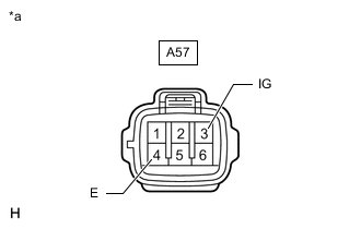
*a Front view of wire harness connector
(to Headlight Cleaner Control Relay)
Disconnect the headlight cleaner control relay connector.
-
Measure the resistance according to the value(s) in the table below.
Standard Resistance Tester Connection Condition Specified Condition A57-4 (E) - Body ground Always Below 1 Ω -
Measure the voltage according to the value(s) in the table below.
Standard Voltage Tester Connection Switch Condition Specified Condition A57-3 (IG) - Body ground Ignition switch ON 11 to 14 V Result Proceed to OK NG
NG
REPAIR OR REPLACE HARNESS OR CONNECTOR
OK
-
-
CHECK HARNESS AND CONNECTOR (HEADLIGHT CLEANER MOTOR AND PUMP ASSEMBLY - HEADLIGHT CLEANER CONTROL RELAY AND BATTERY)
-
Disconnect the A58 headlight cleaner motor and pump assembly connector.
-
Disconnect the A57 headlight cleaner control relay connector.
-
Measure the resistance according to the value(s) in the table below.
Standard Resistance Tester Connection Condition Specified Condition A58-1 - A57-6 (PB) Always Below 1 Ω A58-1 or A57-6 (PB) - Body ground Always 10 kΩ or higher -
Measure the voltage according to the value(s) in the table below.
Standard Voltage Tester Connection Condition Specified Condition A58-2 - Body ground Always 11 to 14 V Result Proceed to OK NG
NG
REPAIR OR REPLACE HARNESS OR CONNECTOR
OK
-
-
CHECK HARNESS AND CONNECTOR (HEADLIGHT LEVELING ECU ASSEMBLY - HEADLIGHT CLEANER CONTROL RELAY)
-
Disconnect the G80 headlight leveling ECU assembly connector.
-
Disconnect the A57 headlight cleaner control relay connector.
-
Measure the resistance according to the value(s) in the table below.
Standard Resistance Tester Connection Condition Specified Condition G80-16 (HLC) - A57-2 (H) Always Below 1 Ω G80-16 (HLC) or A57-2 (H) - Body ground Always 10 kΩ or higher Result Proceed to OK NG
OK
REPLACE HEADLIGHT LEVELING ECU ASSEMBLY Click here
NG
REPAIR OR REPLACE HARNESS OR CONNECTOR
-
-
CHECK HARNESS AND CONNECTOR (HEADLIGHT LEVELING ECU ASSEMBLY - WINDSHIELD WIPER SWITCH ASSEMBLY)
-
Disconnect the G80 headlight light leveling ECU assembly connector.
-
Disconnect the G18 windshield wiper switch assembly connector.
-
Disconnect the A2 windshield washer motor and pump assembly connector.
-
Measure the resistance according to the value(s) in the table below.
Standard Resistance Tester Connection Condition Specified Condition G80-4 (FRWA) - G18-7 (WF) Always Below 1 Ω G80-4 (FRWA) or G18-7 (WF) - Body ground Always 10 kΩ or higher Result Proceed to OK NG
OK
REPLACE HEADLIGHT LEVELING ECU ASSEMBLY Click here
NG
REPAIR OR REPLACE HARNESS OR CONNECTOR
-