REAR DOOR(for Smart Cab) DISASSEMBLY

CAUTION / NOTICE / HINT
Tech Tips
-
Use the same procedure for the RH and LH sides.
-
The procedure listed below is for the LH side.
PROCEDURE
-
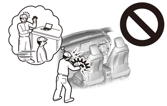
PRECAUTION (w/ Airbag System)
CAUTION:
Be sure to read Precaution thoroughly before servicing.
for Type A:
for Type B:
Note
After turning the ignition switch off, waiting time may be required before disconnecting the cable from the negative (-) battery terminal. Therefore, make sure to read the disconnecting the cable from the negative (-) battery terminal notice before proceeding with work.
-
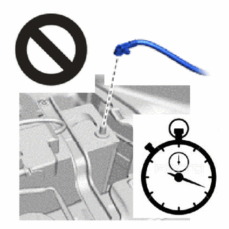
DISCONNECT CABLE FROM NEGATIVE BATTERY TERMINAL (w/ Airbag System)
CAUTION:
-
Wait at least 90 seconds after disconnecting the cable from the negative (-) battery terminal to disable the SRS system.
-
If the airbag deploys for any reason, it may cause a serious accident.
Note
When disconnecting the cable, some systems need to be initialized after the cable is reconnected.
-
-
REMOVE LAP BELT OUTER ANCHOR COVER
-
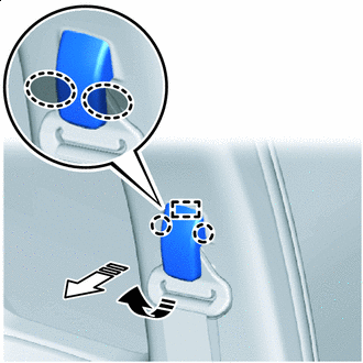
Detach the claw and remove the lap belt outer anchor cover.
-
-
REMOVE REAR DOOR TRIM BOARD SUB-ASSEMBLY LH
-
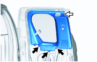
Remove the bolt and disconnect the front seat outer belt floor anchor.
-
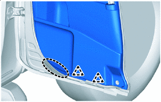

Place Hands Here Detach the clip as shown in the illustration.
-
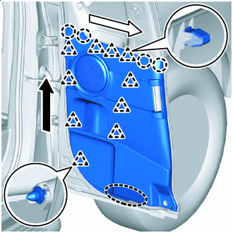
Place Hands Here 
Order of Removal (1) 
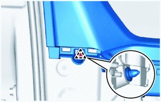
Order of Removal (2) Detach the clip and claw as shown in the illustration.
-

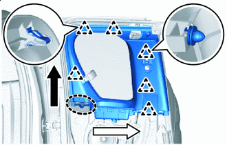
Remove in this Direction (1) 
Remove in this Direction (2) Detach the guide and remove the rear door trim board sub-assembly LH.
-
-
REMOVE SEAT BELT ANCHOR COVER CAP
-
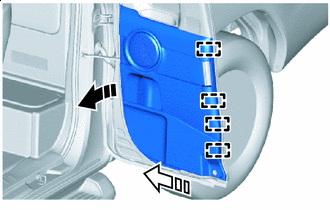
Place Hands Here Remove in this Direction (1) Remove in this Direction (2) Detach the claw and guide and remove the seat belt anchor cover cap as shown in the illustration.
-
-
REMOVE FRONT SEAT OUTER BELT ASSEMBLY LH
-
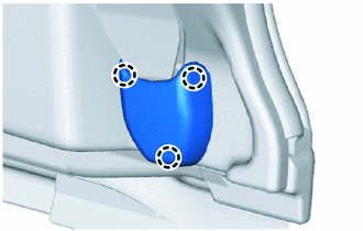
REMOVE REAR DOOR FRAME GARNISH LH
-
Screw Clip Remove the 3 screws and clip.
-
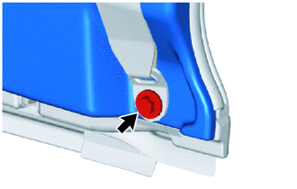
Using a clip remover, detach the clip.
-
Place Hands Here Order of Removal (1) Order of Removal (2) Remove the clip and rear door frame garnish LH.
-
-
REMOVE SCREW GROMMET
-
Using a clip remover, detach the claw and remove the 3 screw grommets.
-
-
REMOVE REAR SPEAKER ASSEMBLY
-
REMOVE ACCESS PANEL INSIDE HANDLE SUB-ASSEMBLY LH
-
*1 Snap Bolt Nut 
Order of Removal Remove in this Direction Detach the snap as shown in the illustration.
-
Remove the nut, bolt and access panel inside handle sub-assembly LH.
-
-
REMOVE UPPER ACCESS PANEL LOCK ASSEMBLY LH
-
REMOVE LOWER ACCESS PANEL LOCK ASSEMBLY LH
-
REMOVE ACCESS PANEL LOCK REMOTE CONTROL ASSEMBLY LH
-
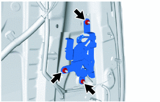
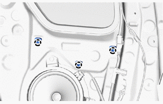
Remove the 3 nuts and access panel lock remote control assembly LH.
-
-
REMOVE QUARTER WINDOW GLASS LH
-
REMOVE QUARTER WINDOW WEATHERSTRIP LH
-
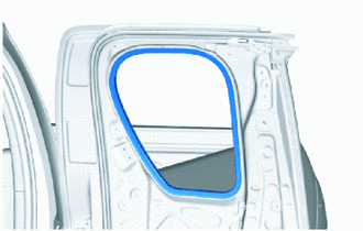
Remove the quarter window weatherstrip LH.
-
-
REMOVE ACCESS PANEL LOCK CANCEL LEVER ASSEMBLY LH
-
Remove the 2 screws and access panel lock cancel lever assembly LH.
-
-
REMOVE FRONT DOOR COURTESY LIGHT SWITCH ASSEMBLY
-
REMOVE ACCESS PANEL LOCK STRIKER PLATE ASSEMBLY
-
Using a T40 "TORX" socket wrench, remove the 2 screws and access panel lock striker plate assembly.
-
-
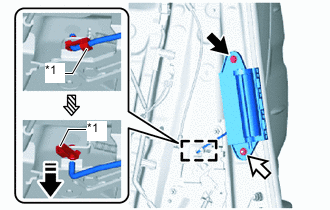
REMOVE ACCESS PANEL CHECK ASSEMBLY LH
-
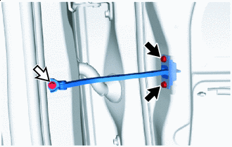
Bolt (A) Bolt (B) Remove the 2 bolts (A), bolt (B) and access panel check assembly LH.
-
-
REMOVE ACCESS PANEL WEATHERSTRIP LH
-
Detach the clip and remove the double-sided tape and access panel weatherstrip LH.
Note
Remove any remaining double-sided tape from the slide door panel LH.
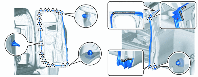

Double-sided Tape - -
-
-
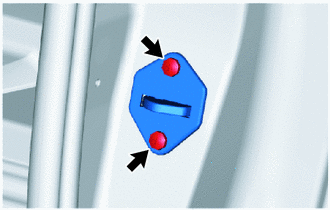
REMOVE REAR DOOR DUST PROOF SEAL
-
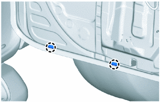
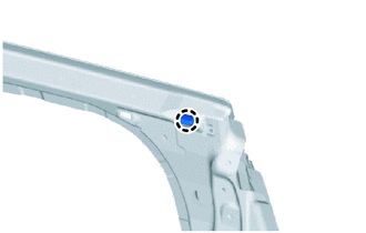
Detach the claw and remove the 2 rear door dust proof seals.
-
-
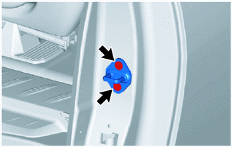
REMOVE REAR DOOR CUSHION
-
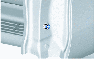
Detach the claw and remove the rear door cushion.
-
-
REMOVE REAR DOOR PANEL CUSHION
-
Detach the claw and remove the rear door panel cushion.
-