WINDSHIELD GLASS REMOVAL
CAUTION / NOTICE / HINT
The necessary procedures (adjustment, calibration, initialization or registration) that must be performed after parts are removed, installed or replaced during the iwindshield glass assembly removal/installation are shown below.
| Replacement Part or Procedure | Necessary Procedures | Effects / Inoperative when not Performed | Link |
|---|---|---|---|
| Disconnect cable from negative battery terminal | Drive the vehicle until stop and start control is permitted (approximately 5 to 60 minutes) | Stop and start system | |
| Memorize steering angle neutral point | Pre-collision system |
Note
When replacing the windshield glass of a vehicle equipped with a forward recognition camera, make sure to use a Toyota genuine part. If a non-Toyota genuine part is used, the forward recognition camera may not be able to be installed due to a missing bracket, or the forward recognition camera system, lane departure alert system, road sign assist system or pre-collision system may not operate properly due to a difference in the transmissivity of the windshield glass or the shape of the black ceramic border.
Tech Tips
-
Use the same procedure for RHD and LHD vehicles.
-
The procedures listed below are for LHD vehicles.
PROCEDURE
-
PRECAUTION
CAUTION:
Be sure to read Precaution thoroughly before servicing.
for Type A:
for Type B:
for Type C:
Note
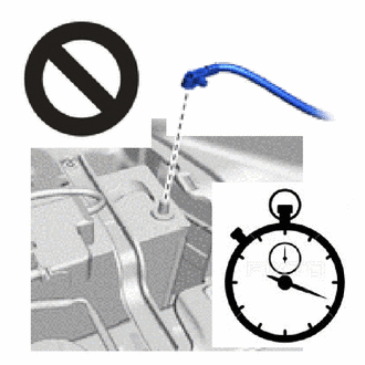
After turning the ignition switch off, waiting time may be required before disconnecting the cable from the negative (-) battery terminal. Therefore, make sure to read the disconnecting the cable from the negative (-) battery terminal notice before proceeding with work.
-
DISCONNECT CABLE FROM NEGATIVE BATTERY TERMINAL
CAUTION:
-
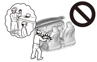
Wait at least 90 seconds after disconnecting the cable from the negative (-) battery terminal to disable the SRS system.
-
If the airbag deploys for any reason, it may cause a serious accident.
Note
When disconnecting the cable, some systems need to be initialized after the cable is reconnected.
-
-
REMOVE FRONT WIPER ARM HEAD CAP
-
REMOVE FRONT WIPER ARM AND BLADE ASSEMBLY LH
-
REMOVE FRONT WIPER ARM AND BLADE ASSEMBLY RH
-
REMOVE FENDER APRON MUDGUARD SEAL SUB-ASSEMBLY LH
-
REMOVE FENDER APRON MUDGUARD SEAL SUB-ASSEMBLY RH
Tech Tips
Use the same procedure described for the LH side.
-
REMOVE FRONT FENDER TO COWL SIDE SEAL LH
-
REMOVE FRONT FENDER TO COWL SIDE SEAL RH
Tech Tips
Use the same procedure described for the LH side.
-
REMOVE COWL TOP VENTILATOR LOUVER SUB-ASSEMBLY
-
REMOVE ASSIST GRIP SUB-ASSEMBLY (w/ Assist Grip)
-
REMOVE FRONT PILLAR GARNISH LH
-
REMOVE FRONT PILLAR GARNISH RH
-
REMOVE NO. 1 FORWARD RECOGNITION COVER (w/ Lane Departure Alert System)
-
REMOVE FORWARD RECOGNITION LATCH (w/ Lane Departure Alert System)
-
REMOVE FORWARD RECOGNITION CAMERA (w/ Lane Departure Alert System)
-
REMOVE FORWARD RECOGNITION HOOD (w/ Camera Heater)
-
REMOVE INNER REAR VIEW MIRROR ASSEMBLY
-
REMOVE MAP LIGHT ASSEMBLY
-
REMOVE NO. 1 ROOM LIGHT ASSEMBLY
-
REMOVE VISOR BRACKET COVER LH
-
REMOVE VISOR BRACKET COVER RH
-
REMOVE VISOR ASSEMBLY LH
-
REMOVE VISOR ASSEMBLY RH
-
REMOVE VISOR HOLDER
-
REMOVE ASSIST GRIP SUB-ASSEMBLY
-
REMOVE ROOF HEADLINING ASSEMBLY
Tech Tips
Remove a sufficient amount of the front portion of the roof headlining assembly so that windshield glass removal and installation procedures can be performed.
-
for Double Cab:
Partially remove the roof headlining assembly.
-
for Single Cab:
Partially remove the roof headlining assembly.
-
for Smart Cab:
Partially remove the roof headlining assembly.
-
-
DISCONNECT ANTENNA CORD SUB-ASSEMBLY (w/ Digital Audio Broadcasting Antenna)
-
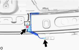
Disconnect the connector.
-
Remove the bolt and detach the clamp.
-
-
REMOVE WINDSHIELD GLASS
Note
-
The windshield glass may fall while performing this procedure. Therefore, use suction cups to hold the windshield glass from the outside of the vehicle.
-
Be careful not to damage the windshield glass when cutting as the windshield glass stopper and No. 2 windshield glass stopper are installed to the windshield glass.
-
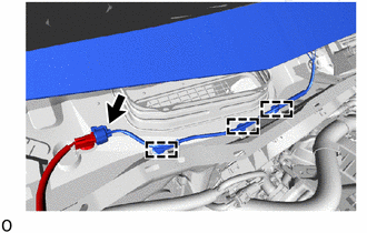
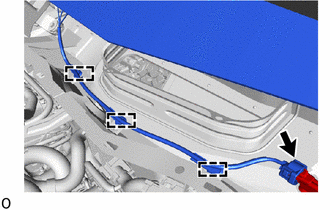
w/ Windshield Deicer System:
-
Disconnect the connector and detach the clamp.
-
for LHD:
-
for RHD:
-
-
-
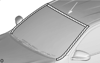

Protective Tape Put protective tape on the body surface around the windshield glass.
-
*a Matchmarks When reusing the windshield glass:
Place adhesive tape on the windshield glass and body panel and use a pen to place matchmarks for installation.
-
Install the suction cups to the windshield glass.
-
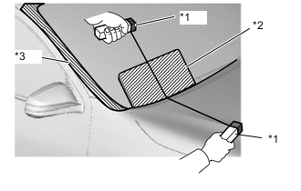
*1 Handles *2 Plastic Sheet *3 Protective Tape Tie objects that can serve as handles (for example, wooden blocks) to both wire ends.
Note
-
When separating the glass from the vehicle, be careful not to damage the vehicle paint or interior/exterior ornaments.
-
To prevent the instrument panel from being scratched when removing the glass, place a plastic sheet between the piano wire and instrument panel.
-
-
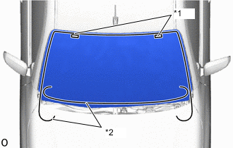
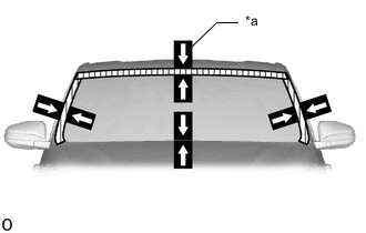
*1 Stopper *2 Piano Wire Insert a piano wire (approximately 0.6 mm) at the locations shown in the illustration.
-
Pull on the ends of the piano wire alternately and leave the stoppers when cutting through the adhesive.
Note
-
Do not forcefully brush the piano wire against the windshield glass.
-
Be careful as the piano wire will break if it crosses itself.
-
-
Using suction cups, detach the 2 windshield glass stoppers to remove the windshield glass.
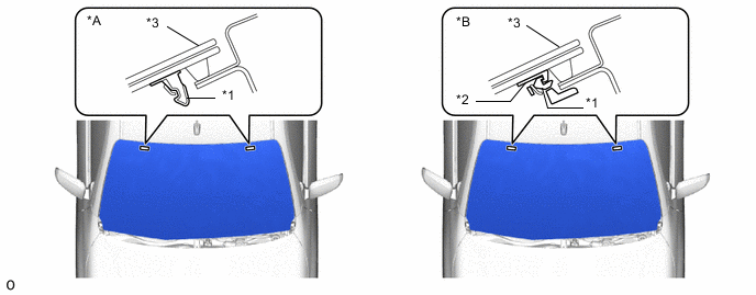
*A for 1-piece Type *B for 2-piece Type *1 Windshield Glass Stopper *2 No. 2 Windshield Glass Stopper *3 Windshield Glass - - Note
-
The windshield glass stoppers and No. 2 windshield glass stoppers are installed on the windshield glass as shown in the illustration. Be careful not to damage the windshield glass when cutting off the adhesive.
-
To prevent the windshield glass from falling when performing this operation, be sure to hold the windshield glass using suction cups.
Tech Tips
Depending on the vehicle, either 1-piece or 2-piece type stoppers may be present.
-
-