Click here
-
-
*1: for LHD
-
*2: for RHD
CHECK POWER WINDOW REGULATOR MASTER SWITCH ASSEMBLY (w/ Entry and Start System)
-
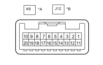
*A for LHD *B for RHD Disconnect the K6*1 or J12*2 power window regulator master switch assembly connector.
-
Measure the voltage and resistance according to the value(s) in the table below.
Tip:Measure the values on the wire harness side with the connector disconnected.
Table 1. for LHD Tester Connection Wiring Color Terminal Description Condition Specified Condition K6-11 (B) - K6-12 (GND) Y - W-B Power supply Always 11 to 14 V K6-12 (GND) - Body ground W-B - Body ground Ground Always Below 1 Ω Table 2. for RHD Tester Connection Wiring Color Terminal Description Condition Specified Condition J12-11 (B) - J12-12 (GND) Y - W-B Power supply Always 11 to 14 V J12-12 (GND) - Body ground W-B - Body ground Ground Always Below 1 Ω -
Reconnect the K6*1 or J12*2 power window regulator master switch assembly connector.
-
Measure the voltage according to the value(s) in the table below.
Table 3. for LHD Tester Connection Wiring Color Terminal Description Condition Specified Condition K6-15 (DOWN) - K6-12 (GND) P - W-B Driver door power window motor DOWN output Ignition switch ON, driver door power window regulator switch not pushed or pulled 11 to 14 V Ignition switch ON, driver door power window moving, driver door power window regulator switch pushed halfway down (Manual operation) Below 1 V K6-20 (UP) - K6-12 (GND) B - W-B Driver door power window motor UP output Ignition switch ON, driver door power window regulator switch not pushed or pulled 11 to 14 V Ignition switch ON, driver door power window moving, driver door power window regulator switch pulled halfway up (Manual operation) Below 1 V Table 4. for RHD Tester Connection Wiring Color Terminal Description Condition Specified Condition J12-15 (DOWN) - J12-12 (GND) P - W-B Driver door power window motor DOWN output Ignition switch ON, driver door power window regulator switch not pushed or pulled 11 to 14 V Ignition switch ON, driver door power window moving, driver door power window regulator switch pushed halfway down (Manual operation) Below 1 V J12-20 (UP) - J12-12 (GND) B - W-B Driver door power window motor UP output Ignition switch ON, driver door power window regulator switch not pushed or pulled 11 to 14 V Ignition switch ON, driver door power window moving, driver door power window regulator switch pulled halfway up (Manual operation) Below 1 V
-
-
-
*1: for LHD
-
*2: for RHD
CHECK POWER WINDOW REGULATOR MASTER SWITCH ASSEMBLY (for Models with Jam Protection Function on Driver Door Window Only)
-
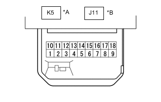
*A for LHD *B for RHD Disconnect the K5*1 or J11*2 power window regulator master switch assembly connector.
-
Measure the voltage and resistance according to the value(s) in the table below.
Tip:Measure the values on the wire harness side with the connector disconnected.
Table 5. for LHD Tester Connection Wiring Color Terminal Description Condition Specified Condition K5-7 (B) - K5-1 (E) LA-GR - W-B IG power supply Ignition switch ON 11 to 14 V Ignition switch off Below 1 V K5-1 (E) - Body ground W-B - Body ground Ground Always Below 1 Ω Table 6. for RHD Tester Connection Wiring Color Terminal Description Condition Specified Condition J11-7 (B) - J11-9 (E) LA-GR - W-B IG power supply Ignition switch ON 11 to 14 V Ignition switch off Below 1 V J11-9 (E) - Body ground W-B - Body ground Ground Always Below 1 Ω -
Reconnect the K5*1 or J11*2 power window regulator master switch assembly connector.
-
Measure the voltage according to the value(s) in the table below.
Table 7. for LHD Tester Connection Wiring Color Terminal Description Condition Specified Condition K5-6 (U) - K5-1 (E) B - W-B Driver door power window motor up output Ignition switch ON, driver door power window switch not pushed or pulled 11 to 14 V Ignition switch ON, driver door power window switch pulled halfway up (Manual operation) Below 1 V K5-4 (A) - K5-1 (E) SB - W-B Driver door power window motor auto up output Ignition switch ON, driver door power window fully open 11 to 14 V Ignition switch ON, driver door power window switch fully pulled up (AUTO UP position) Below 1 V Ignition switch ON, driver door power window fully closed 11 to 14 V Driver door power window motor auto down output Ignition switch ON, driver door power window fully closed 11 to 14 V Ignition switch ON, driver door power window switch fully pushed down (AUTO DOWN position) Below 1 V Ignition switch ON, driver door power window fully open 11 to 14 V K5-3 (D) - K5-1 (E) P - W-B Driver door power window motor down output Ignition switch ON, driver door power window switch not pushed or pulled 11 to 14 V Ignition switch ON, driver door power window switch pushed halfway down (Manual operation) Below 1 V K5-10 (U) - K5-1 (E) LA-R - W-B Front passenger door power window motor up output Ignition switch ON, front passenger door power window switch not pushed or pulled 11 to 14 V Ignition switch ON, front passenger door power window switch pulled up (Manual operation) Below 1 V K5-18 (D) - K5-1 (E) LA-G - W-B Front passenger door power window motor down output Ignition switch ON, front passenger door power window switch not pushed or pulled 11 to 14 V Ignition switch ON, front passenger door power window switch pushed down (Manual operation) Below 1 V K5-12 (U) - K5-1 (E)* LA-Y - W-B Rear door LH power window motor up output Ignition switch ON, rear LH door power window switch not pushed or pulled 11 to 14 V Ignition switch ON, rear LH door power window switch pulled up (Manual operation) Below 1 V K5-13 (D) - K5-1 (E)* LA-P - W-B Rear door LH power window motor down output Ignition switch ON, rear LH door power window switch not pushed or pulled 11 to 14 V Ignition switch ON, rear LH door power window switch pushed down (Manual operation) Below 1 V K5-15 (U) - K5-1 (E)* LA-B - W-B Rear door RH power window motor up output Ignition switch ON, rear RH door power window switch not pushed or pulled 11 to 14 V Ignition switch ON, rear RH door power window switch pulled up (Manual operation) Below 1 V K5-16 (D) - K5-1 (E)* LA-V - W-B Rear door RH power window motor down output Ignition switch ON, rear RH door power window switch not pushed or pulled 11 to 14 V Ignition switch ON, rear RH door power window switch pushed down (Manual operation) Below 1 V *: for Double Cab
Table 8. for RHD Tester Connection Wiring Color Terminal Description Condition Specified Condition J11-3 (U) - J11-9 (E) B - W-B Driver door power window motor up output Ignition switch ON, driver door power window switch not pushed or pulled 11 to 14 V Ignition switch ON, driver door power window switch pulled halfway up (Manual operation) Below 1 V J11-4 (A) - J11-9 (E) SB - W-B Driver door power window motor auto up output Ignition switch ON, driver door power window fully open 11 to 14 V Ignition switch ON, driver door power window switch fully pulled up (AUTO UP position) Below 1 V Ignition switch ON, driver door power window fully closed 11 to 14 V Driver door power window motor auto down output Ignition switch ON, driver door power window fully closed 11 to 14 V Ignition switch ON, driver door power window switch fully pushed down (AUTO DOWN position) Below 1 V Ignition switch ON, driver door power window fully open 11 to 14 V J11-6 (D) - J11-9 (E) P - W-B Driver door power window motor down output Ignition switch ON, driver door power window switch not pushed or pulled 11 to 14 V Ignition switch ON, driver door power window switch pushed halfway down (Manual operation) Below 1 V J11-10 (U) - J11-9 (E) LA-R - W-B Front passenger door power window motor up output Ignition switch ON, front passenger door power window switch not pushed or pulled 11 to 14 V Ignition switch ON, front passenger door power window switch pulled up (Manual operation) Below 1 V J11-18 (D) - J11-9 (E) LA-G - W-B Front passenger door power window motor down output Ignition switch ON, front passenger door power window switch not pushed or pulled 11 to 14 V Ignition switch ON, front passenger door power window switch pushed down (Manual operation) Below 1 V J11-12 (U) - J11-9 (E)* LA-Y - W-B Rear door LH power window motor up output Ignition switch ON, rear LH door power window switch not pushed or pulled 11 to 14 V Ignition switch ON, rear LH door power window switch pulled up (Manual operation) Below 1 V J11-13 (D) - J11-9 (E)* LA-P - W-B Rear door LH power window motor down output Ignition switch ON, rear LH door power window switch not pushed or pulled 11 to 14 V Ignition switch ON, rear LH door power window switch pushed down (Manual operation) Below 1 V J11-15 (U) - J11-9 (E)* LA-B - W-B Rear door RH power window motor up output Ignition switch ON, rear RH door power window switch not pushed or pulled 11 to 14 V Ignition switch ON, rear RH door power window switch pulled up (Manual operation) Below 1 V J11-16 (D) - J11-9 (E)* LA-V - W-B Rear door RH power window motor down output Ignition switch ON, rear RH door power window switch not pushed or pulled 11 to 14 V Ignition switch ON, rear RH door power window switch pushed down (Manual operation) Below 1 V *: for Double Cab
-
-
CHECK FRONT POWER WINDOW REGULATOR MOTOR ASSEMBLY RH (w/ Entry and Start System)
-

Disconnect the J9 front power window regulator motor assembly RH connector.
-
Measure the voltage and resistance according to the value(s) in the table below.
Tip:Measure the values on the wire harness side with the connector disconnected.
Tester Connection Wiring Color Terminal Description Condition Specified Condition J9-1 (GND) - Body ground W-B - Body ground*1
LA-W - Body ground*2
Ground Always Below 1 Ω J9-2 (B) - Body ground GR - Body ground*1
LA-GR - Body ground*2
Power supply Always 11 to 14 V *1: for LHD
*2: for RHD
-
Reconnect the J9 front power window regulator motor assembly RH connector.
-
Measure the voltage according to the value(s) in the table below.
Table 9. for LHD Tester Connection Wiring Color Terminal Description Condition Specified Condition J9-4 (AUTO) - J9-1 (GND) L - W-B Power window motor AUTO UP input Ignition switch ON, front passenger door power window fully open 11 to 14 V Ignition switch ON, front passenger door power window moving, power window regulator switch assembly fully pulled up (Auto operation) Below 1 V Ignition switch ON, front passenger door power window fully closed 11 to 14 V Power window motor AUTO DOWN input Ignition switch ON, front passenger door power window fully closed 11 to 14 V Ignition switch ON, front passenger door power window moving, power window regulator switch assembly fully pushed down (Auto operation) Below 1 V Ignition switch ON, front passenger door power window fully open 11 to 14 V J9-7 (DOWN) - J9-1 (GND) P - W-B Power window motor DOWN input Ignition switch ON, power window regulator switch assembly not pushed or pulled 11 to 14 V Ignition switch ON, front passenger door power window moving, power window regulator switch assembly pushed halfway down (Manual operation) Below 1 V Ignition switch ON, front passenger door power window fully closed 11 to 14 V Ignition switch ON, front passenger door power window moving, power window regulator switch assembly fully pushed down (Auto operation) Below 1 V Ignition switch ON, front passenger door power window fully open 11 to 14 V J9-10 (UP) - J9-1 (GND) B - W-B Power window motor UP input Ignition switch ON, power window regulator switch assembly not pushed or pulled 11 to 14 V Ignition switch ON, front passenger door power window moving, power window regulator switch assembly pulled halfway up (Manual operation) Below 1 V Ignition switch ON, front passenger door power window fully open 11 to 14 V Ignition switch ON, front passenger door power window moving, power window regulator switch assembly fully pulled up (Auto operation) Below 1 V Ignition switch ON, front passenger door power window fully closed 11 to 14 V Table 10. for RHD Tester Connection Wiring Color Terminal Description Condition Specified Condition J9-7 (DOWN) - J9-1 (GND) P - LA-W Power window motor DOWN input Ignition switch ON, power window master switch (driver door power window regulator switch) not pushed or pulled 11 to 14 V Ignition switch ON, driver door power window moving, power window master switch (driver door power window regulator switch) pushed halfway down (Manual operation) Below 1 V Ignition switch ON, driver door power window fully closed 11 to 14 V Ignition switch ON, driver door power window moving, power window master switch (driver door power window regulator switch) fully pushed down (Auto operation) Below 1 V Ignition switch ON, driver door power window fully open 11 to 14 V J9-10 (UP) - J9-1 (GND) B - LA-W Power window motor UP input Ignition switch ON, power window master switch (driver door power window regulator switch) not pushed or pulled 11 to 14 V Ignition switch ON, driver door power window moving, power window master switch (driver door power window regulator switch) pulled halfway up (Manual operation) Below 1 V Ignition switch ON, power window master switch (driver door power window regulator switch) fully open 11 to 14 V Ignition switch ON, driver door power window moving, power window master switch (driver door power window regulator switch) fully pulled up (Auto operation) Below 1 V Ignition switch ON, driver door power window fully closed 11 to 14 V
-
-
CHECK FRONT POWER WINDOW REGULATOR MOTOR ASSEMBLY RH (for Models with Jam Protection Function on Driver Door Only, RHD)
-

Disconnect the J9 front power window regulator motor assembly RH connector.
-
Measure the voltage and resistance according to the value(s) in the table below.
Tip:Measure the values on the wire harness side with the connector disconnected.
Tester Connection Wiring Color Terminal Description Condition Specified Condition J9-1 (GND) - Body ground W-B - Body ground Ground Always Below 1 Ω J9-2 (B) - Body ground GR - Body ground Power supply Always 11 to 14 V -
Reconnect the J9 front power window regulator motor assembly RH connector.
-
Measure the voltage according to the value(s) in the table below.
Tester Connection Wiring Color Terminal Description Condition Specified Condition J9-7 (DOWN) - J9-1 (GND) P - W-B Power window motor DOWN input Ignition switch ON, power window master switch (driver door power window regulator switch) not pushed or pulled 11 to 14 V Ignition switch ON, driver door power window moving, power window master switch (driver door power window regulator switch) pushed halfway down (Manual operation) Below 1 V Ignition switch ON, driver door power window fully closed 11 to 14 V Ignition switch ON, driver door power window moving, power window master switch (driver door power window regulator switch) fully pushed down (Auto operation) Below 1 V Ignition switch ON, driver door power window fully open 11 to 14 V J9-10 (UP) - J9-1 (GND) B - W-B Power window motor UP input Ignition switch ON, power window master switch (driver door power window regulator switch) not pushed or pulled 11 to 14 V Ignition switch ON, driver door power window moving, power window master switch (driver door power window regulator switch) pulled halfway up (Manual operation) Below 1 V Ignition switch ON, power window master switch (driver door power window regulator switch) fully open 11 to 14 V Ignition switch ON, driver door power window moving, power window master switch (driver door power window regulator switch) fully pulled up (Auto operation) Below 1 V Ignition switch ON, driver door power window fully closed 11 to 14 V
-
-
CHECK FRONT POWER WINDOW REGULATOR MOTOR ASSEMBLY LH (w/ Entry and Start System)
-

Disconnect the K9 front power window regulator motor assembly LH connector.
-
Measure the voltage and resistance according to the value(s) in the table below.
Tip:Measure the values on the wire harness side with the connector disconnected.
Tester Connection Wiring Color Terminal Description Condition Specified Condition K9-1 (GND) - Body ground LA-W - Body ground*1
W-B - Body ground*2
Ground Always Below 1 Ω K9-2 (B) - Body ground LA-GR - Body ground*1
GR - Body ground*2
Power supply Always 11 to 14 V *1: for LHD
*2: for RHD
-
Reconnect the K9 front power window regulator motor assembly LH connector.
-
Measure the voltage according to the value(s) in the table below.
Table 11. for LHD Tester Connection Wiring Color Terminal Description Condition Specified Condition K9-7 (DOWN) - K9-1 (GND) P - LA-W Power window motor DOWN input Ignition switch ON, power window master switch (driver door power window regulator switch) not pushed or pulled 11 to 14 V Ignition switch ON, driver door power window moving, power window master switch (driver door power window regulator switch) pushed halfway down (Manual operation) Below 1 V Ignition switch ON, driver door power window fully closed 11 to 14 V Ignition switch ON, driver door power window moving, power window master switch (driver door power window regulator switch) fully pushed down (Auto operation) Below 1 V Ignition switch ON, driver door power window fully open 11 to 14 V K9-10 (UP) - K9-1 (GND) B - LA-W Power window motor UP input Ignition switch ON, power window master switch (driver door power window regulator switch) not pushed or pulled 11 to 14 V Ignition switch ON, driver door power window moving, power window master switch (driver door power window regulator switch) pulled halfway up (Manual operation) Below 1 V Ignition switch ON, power window master switch (driver door power window regulator switch) fully open 11 to 14 V Ignition switch ON, driver door power window moving, power window master switch (driver door power window regulator switch) fully pulled up (Auto operation) Below 1 V Ignition switch ON, driver door power window fully closed 11 to 14 V Table 12. for RHD Tester Connection Wiring Color Terminal Description Condition Specified Condition K9-4 (AUTO) - K9-1 (GND) L - W-B Power window motor AUTO UP input Ignition switch ON, front passenger door power window fully open 11 to 14 V Ignition switch ON, front passenger door power window moving, power window regulator switch assembly fully pulled up (Auto operation) Below 1 V Ignition switch ON, front passenger door power window fully closed 11 to 14 V Power window motor AUTO DOWN input Ignition switch ON, front passenger door power window fully closed 11 to 14 V Ignition switch ON, front passenger door power window moving, power window regulator switch assembly fully pushed down (Auto operation) Below 1 V Ignition switch ON, front passenger door power window fully open 11 to 14 V K9-7 (DOWN) - K9-1 (GND) P - W-B Power window motor DOWN input Ignition switch ON, power window regulator switch assembly not pushed or pulled 11 to 14 V Ignition switch ON, front passenger door power window moving, power window regulator switch assembly pushed halfway down (Manual operation) Below 1 V Ignition switch ON, front passenger door power window fully closed 11 to 14 V Ignition switch ON, front passenger door power window moving, power window regulator switch assembly fully pushed down (Auto operation) Below 1 V Ignition switch ON, front passenger door power window fully open 11 to 14 V K9-10 (UP) - K9-1 (GND) B - W-B Power window motor UP input Ignition switch ON, power window regulator switch assembly not pushed or pulled 11 to 14 V Ignition switch ON, front passenger door power window moving, power window regulator switch assembly pulled halfway up (Manual operation) Below 1 V Ignition switch ON, front passenger door power window fully open 11 to 14 V Ignition switch ON, front passenger door power window moving, power window regulator switch assembly fully pulled up (Auto operation) Below 1 V Ignition switch ON, front passenger door power window fully closed 11 to 14 V
-
-
CHECK FRONT POWER WINDOW REGULATOR MOTOR ASSEMBLY LH (for Models with Jam Protection Function on Driver Door Only, LHD)
-

Disconnect the K9 front power window regulator motor assembly LH connector.
-
Measure the voltage and resistance according to the value(s) in the table below.
Tip:Measure the values on the wire harness side with the connector disconnected.
Tester Connection Wiring Color Terminal Description Condition Specified Condition K9-1 (GND) - Body ground W-B - Body ground Ground Always Below 1 Ω K9-2 (B) - Body ground GR - Body ground Power supply Always 11 to 14 V -
Reconnect the K9 front power window regulator motor assembly LH connector.
-
Measure the voltage according to the value(s) in the table below.
Tester Connection Wiring Color Terminal Description Condition Specified Condition K9-7 (DOWN) - K9-1 (GND) P - W-B Power window motor DOWN input Ignition switch ON, power window master switch (driver door power window regulator switch) not pushed or pulled 11 to 14 V Ignition switch ON, driver door power window moving, power window master switch (driver door power window regulator switch) pushed halfway down (Manual operation) Below 1 V Ignition switch ON, driver door power window fully closed 11 to 14 V Ignition switch ON, driver door power window moving, power window master switch (driver door power window regulator switch) fully pushed down (Auto operation) Below 1 V Ignition switch ON, driver door power window fully open 11 to 14 V K9-10 (UP) - K9-1 (GND) B - W-B Power window motor UP input Ignition switch ON, power window master switch (driver door power window regulator switch) not pushed or pulled 11 to 14 V Ignition switch ON, driver door power window moving, power window master switch (driver door power window regulator switch) pulled halfway up (Manual operation) Below 1 V Ignition switch ON, power window master switch (driver door power window regulator switch) fully open 11 to 14 V Ignition switch ON, driver door power window moving, power window master switch (driver door power window regulator switch) fully pulled up (Auto operation) Below 1 V Ignition switch ON, driver door power window fully closed 11 to 14 V
-
-
CHECK REAR POWER WINDOW REGULATOR MOTOR ASSEMBLY LH (w/ Entry and Start System)
-
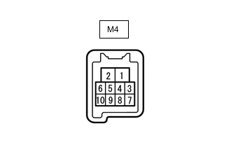
Disconnect the M4 rear power window regulator motor assembly LH connector.
-
Measure the voltage and resistance according to the value(s) in the table below.
Tip:Measure the values on the wire harness side with the connector disconnected.
Tester Connection Wiring Color Terminal Description Condition Specified Condition M4-1 (GND) - Body ground W-B - Body ground Ground Always Below 1 Ω M4-2 (B) - Body ground L - Body ground Power supply Always 11 to 14 V -
Reconnect the M4 rear power window regulator motor assembly LH connector.
-
Measure the voltage according to the value(s) in the table below.
Tester Connection Wiring Color Terminal Description Condition Specified Condition M4-4 (AUTO) - M4-1 (GND) R - W-B Power window motor AUTO UP input Ignition switch ON, rear LH door power window fully open 11 to 14 V Ignition switch ON, rear LH door power window moving, rear power window regulator switch assembly (for Rear LH Door) fully pulled up (Auto operation) Below 1 V Ignition switch ON, rear LH door power window fully closed 11 to 14 V Power window motor AUTO DOWN input Ignition switch ON, rear LH door power window fully closed 11 to 14 V Ignition switch ON, rear LH door power window moving, rear power window regulator switch assembly (for Rear LH Door) fully pushed down (Auto operation) Below 1 V Ignition switch ON, rear LH door power window fully open 11 to 14 V M4-7 (DOWN) - M4-1 (GND) P - W-B Power window motor DOWN input Ignition switch ON, rear power window regulator switch assembly (for Rear LH Door) not pushed or pulled 11 to 14 V Ignition switch ON, rear LH door power window moving, rear power window regulator switch assembly (for Rear LH Door) pushed halfway down (Manual operation) Below 1 V Ignition switch ON, rear LH door power window fully closed 11 to 14 V Ignition switch ON, rear LH door power window moving, rear power window regulator switch assembly (for Rear LH Door) fully pushed down (Auto operation) Below 1 V Ignition switch ON, rear LH door power window fully open 11 to 14 V M4-10 (UP) - M4-1 (GND) B - W-B Power window motor UP input Ignition switch ON, rear power window regulator switch assembly (for Rear LH Door) not pushed or pulled 11 to 14 V Ignition switch ON, rear LH door power window moving, rear power window regulator switch assembly (for Rear LH Door) pulled halfway up (Manual operation) Below 1 V Ignition switch ON, rear LH door power window fully open 11 to 14 V Ignition switch ON, rear LH door power window moving, rear power window regulator switch assembly (for Rear LH Door) fully pulled up (Auto operation) Below 1 V Ignition switch ON, rear LH door power window fully closed 11 to 14 V
-
-
CHECK REAR POWER WINDOW REGULATOR MOTOR ASSEMBLY RH (w/ Entry and Start System)
-

Disconnect the L4 rear power window regulator motor assembly RH connector.
-
Measure the voltage and resistance according to the value(s) in the table below.
Tip:Measure the values on the wire harness side with the connector disconnected.
Tester Connection Wiring Color Terminal Description Condition Specified Condition L4-1 (GND) - Body ground W-B - Body ground Ground Always Below 1 Ω L4-2 (B) - Body ground G - Body ground Power supply Always 11 to 14 V -
Reconnect the L4 rear power window regulator motor assembly RH connector.
-
Measure the voltage according to the value(s) in the table below.
Tester Connection Wiring Color Terminal Description Condition Specified Condition L4-4 (AUTO) - L4-1 (GND) R - W-B Power window motor AUTO UP input Ignition switch ON, rear RH door power window fully open 11 to 14 V Ignition switch ON, rear RH door power window moving, rear power window regulator switch assembly (for Rear RH Door) fully pulled up (Auto operation) Below 1 V Ignition switch ON, rear RH door power window fully closed 11 to 14 V Power window motor AUTO DOWN input Ignition switch ON, rear RH door power window fully closed 11 to 14 V Ignition switch ON, rear RH door power window moving, rear power window regulator switch assembly (for Rear RH Door) fully pushed down (Auto operation) Below 1 V Ignition switch ON, rear RH door power window fully open 11 to 14 V L4-7 (DOWN) - L4-1 (GND) P - W-B Power window motor DOWN input Ignition switch ON, rear power window regulator switch assembly (for Rear RH Door) not pushed or pulled 11 to 14 V Ignition switch ON, rear RH door power window moving, rear power window regulator switch assembly (for Rear RH Door) pushed halfway down (Manual operation) Below 1 V Ignition switch ON, rear RH door power window fully closed 11 to 14 V Ignition switch ON, rear RH door power window moving, rear power window regulator switch assembly (for Rear RH Door) fully pushed down (Auto operation) Below 1 V Ignition switch ON, rear RH door power window fully open 11 to 14 V L4-10 (UP) - L4-1 (GND) B - W-B Power window motor UP input Ignition switch ON, rear power window regulator switch assembly (for Rear RH Door) not pushed or pulled 11 to 14 V Ignition switch ON, rear RH door power window moving, rear power window regulator switch assembly (for Rear RH Door) pulled halfway up (Manual operation) Below 1 V Ignition switch ON, rear RH door power window fully open 11 to 14 V Ignition switch ON, rear RH door power window moving, rear power window regulator switch assembly (for Rear RH Door) fully pulled up (Auto operation) Below 1 V Ignition switch ON, rear RH door power window fully closed 11 to 14 V
-
-
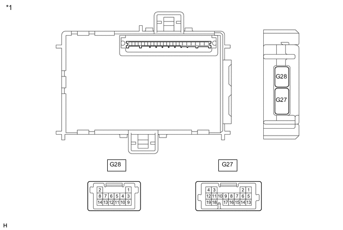
*1 Body ECU - - 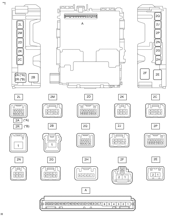
*A for LHD *B for RHD *1 Instrument Panel Junction Block Assembly - - CHECK INSTRUMENT PANEL JUNCTION BLOCK ASSEMBLY AND BODY ECU
-
Remove the body ECU from the instrument panel junction block assembly.
-
for LHD:
-
for RHD:
-
-
Measure the voltage and resistance according to the value(s) in the table below.
Tester Connection Wiring Color Terminal Description Condition Specified Condition A-1 (GND) - Body ground None - Body ground Ground Always Below 1 Ω A-6 (BECU) - Body ground None - Body ground Battery power supply Always 11 to 14 V A-7 (IG) - Body ground None - Body ground IG power supply Ignition switch ON 11 to 14 V Ignition switch off Below 1 V -
Install the body ECU to the instrument panel junction block assembly.
-
for LHD:
-
for RHD:
-
-
Measure the voltage and waveform according to the value(s) in the table below.
Tester Connection Wiring Color Terminal Description Condition Specified Condition G27-14 (PCTY) - Body ground LG - Body ground Front passenger door courtesy light switch input Front passenger door open Below 1 V Front passenger door closed Pulse generation 2L-4 (DCTY) - Body ground R - Body ground Driver door courtesy light switch input Driver door open Below 1 V Driver door closed Pulse generation
-