POWER POINT SOCKET(for Double Socket Type) INSTALLATION
CAUTION / NOTICE / HINT
Tech Tips
-
Use the same procedure for RHD and LHD vehicles.
-
The procedures listed below are for LHD vehicles.
PROCEDURE
-
INSTALL NO. 1 POWER OUTLET SOCKET COVER
Tech Tips
Use the same procedure for both power outlet socket covers.
-

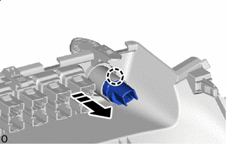
Install in this Direction Attach the claw to install the No. 1 power outlet socket cover as shown in the illustration.
-
-
INSTALL NO. 1 POWER OUTLET SOCKET ASSEMBLY
Tech Tips
Use the same procedure for both power outlet socket assemblies.
-
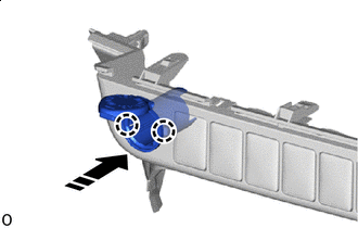
Install in this Direction Attach the claw to install the No. 1 power outlet socket assembly as shown in the illustration.
-
-
INSTALL LOWER INSTRUMENT COVER SUB-ASSEMBLY
-
INSTALL LOWER NO. 1 INSTRUMENT PANEL AIR BAG ASSEMBLY (w/ Knee Airbag)
-
INSTALL NO. 1 INSTRUMENT PANEL UNDER COVER SUB-ASSEMBLY (w/ Knee Airbag)
-
INSTALL LOWER INSTRUMENT PANEL FINISH PANEL SUB-ASSEMBLY (w/o Knee Airbag)
-
INSTALL STEERING COLUMN LOWER COVER
-
INSTALL INTEGRATION PANEL SUB-ASSEMBLY
-
for Manual Cooler System:
-
for Manual Air Conditioning System:
-
-
INSTALL AIR INLET DAMPER CONTROL LEVER
-
for Manual Cooler System:
-
for Manual Air Conditioning System:
-
-
INSTALL CONTROL KNOB SUB-ASSEMBLY
-
for Manual Cooler System:
-
for Manual Air Conditioning System:
-
-
INSTALL AIR CONDITIONING CONTROL ASSEMBLY (for Automatic Air Conditioning System)
-
INSTALL CONSOLE BOX ASSEMBLY (w/ Console Box Lid)
-
INSTALL CONSOLE BOX ASSEMBLY (w/o Console Box Lid)
-
INSTALL INSTRUMENT CLUSTER FINISH PANEL ASSEMBLY
-
INSTALL STEERING WHEEL ASSEMBLY
-
CONNECT CABLE TO NEGATIVE BATTERY TERMINAL (w/ Airbag System)
Note
When disconnecting the cable, some systems need to be initialized after the cable is reconnected.
-
CHECK SRS WARNING LIGHT (w/ Airbag System)
for Type A:
for Type B:
for Type C: